I'm looking at a datasheet for a digital circuit and it specifies that the typical input hysteresis is 100 mV. What does this mean exactly?
Asked
Active
Viewed 2.8k times
6 Answers
28
Let's say you detect a low-to-high transition at 2.5 V. A 100 mV hysteresis would mean that the low-to-high transition is detected at 2.55 V and the high-to-low transition is detected at 2.45 V, a 100 mV difference.
Hysteresis is used to prevent several quickly successive changes if the input signal would contain some noise, for example. The noise could mean you cross the threshold of 2.5 V more than just once, which you don't want.
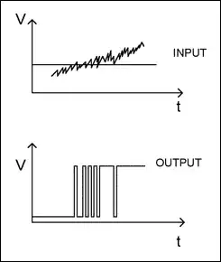
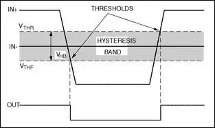
A 100 mV hysteresis means that noise levels less than 100 mV won't influence the threshold passing. Which threshold applies depends on whether you go from low to high (then it's the higher threshold) or from high to low (then it's the lower one):
edit
Another way to illustrate hysteresis is through its transfer function, with the typical loop:
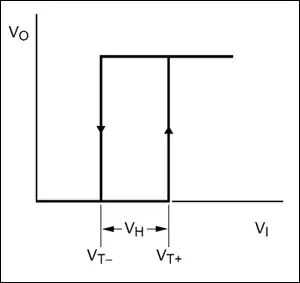
As long as the input voltage remains below \$V_{T+}\$ the output is low, but if it exceeds this value the output switches to high (the up-going arrow). Then the output remains high as long as the input voltage stays above \$V_{T-}\$. When the input voltage drops below this threshold the output switches to a low level (the down-going arrow).
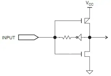
Note: hysteresis can also be used for other purposes than increasing noise immunity. The inverter below has a hysteresis input (which makes it a Schmitt trigger, indicated by the symbol inside the inverter). This simple circuit is all you need to make an oscillator.
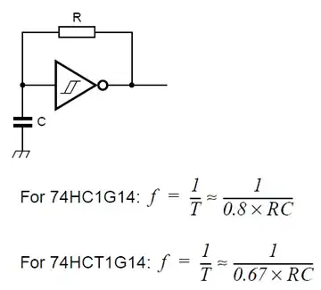
Here's how it works. When it's switched on the capacitor's voltage is zero, so the output is high (it's an inverter!). The high output voltage starts charging the capacitor through R. When the voltage over the capacitor reaches the higher threshold the inverter sees this as a high voltage, and the output will go low. The capacitor will now discharge to the low output via R until the lower threshold is reached. The inverter will then again see this as a low voltage, and make the output high, so the capacitor starts to charge again, and the whole thing repeats.
The frequency is determined by the capacitor's and resistor's value as given in the equations. The difference between the frequency for the normal HCMOS (HC) and the TTL-compatible (HCT) is because the threshold levels are different for both parts.
stevenvh
- 145,145
- 21
- 455
- 667
-
3@umps using hysteresis in the way stevenvh is describing is known as a Schmitt trigger. Just thought I would add. http://en.wikipedia.org/wiki/Schmitt_trigger – Richard May 31 '11 at 18:52
7
The other two answers give an example of what hysteresis means in a particular case where there is a discrete trigger, but hysteresis has a more general meaning in the continuous domain, which is the following:
A system is said to exhibit hysteresis when measurements taken in one "direction" are not necessarily equal to measurements of the "same thing" taken in the other "direction".
For instance, imagine you have a potentiometer with markings from 0 to 9. The potentiometer could be said to exhibit hysteresis if when turned to "5" in the clockwise direction, the actual resistance were 5.1kΩ while when turned to "5" in the counter-clockwise direction, the actual resistance were 4.9kΩ. Unlike the discrete example, the same effect might be present when the knob is turned to "4". Or the effect could be the opposite at "4"!
That's a 1-dimensonal case. You can imagine 2-dimensional hysteresis in the case of, for instance, a sensor consisting of a sheet of material that can sense stretch or strain in two nearly orthogonal directions.
terrace
- 1,334
- 1
- 15
- 28
4
Hysteresis in a circuit arises when an input above a certain level triggers an output, but the output isn't reset until the input reaches a lower level. With an input between those values, the output remains the same (high or low). The difference between the two input values is the hysteresis. It typically occurs in circuits with positive feedback. An example of a circuit with hysteresis is a Schmitt trigger.
Leon Heller
- 38,774
- 2
- 60
- 96
1
This is tangentially related, but it is a mechanism by which ICs can provide input hysteresis; some chip inputs have "pin keeper" circuits. They generate a weak positive feedback out the pin which aids in preserving state. However, the hysteresis range varies depending on the input impedance. Providing the pin-keeper a signal with no impedance would have no hysteresis, while giving it a signal with impedance higher than the feedback resistor would mean it's unable to change the state at all.
Adapted from an Atmel CPLD datasheet
1
If you have ever had one of those nightlight hall light things you plug in a wall socket that has a light sensor, when it gets dark it turns the light on, but its own light turns the light off, then it is dark and it turns the light on. But it is so fast that it just flickers, can be headache inducing for some folks.
Now think about a digital thermostat for your house. Imagine if it were poorly placed right in line with an air conditioner vent. You have it set for some temp like 72 degrees. Imagine that when it reads 73 it turns the A/C on, but as soon as the A/C turns on it cools it back down into the 72 range and turns it off. Not as fast as the light sensor nightlight but not a great design. Instead what you will see is a well placed or at least better placed thermostat, that when it switches from 72 to 73 it kicks the A/C on, but wont turn it off until it drops down into 72 then down below 72 into 71. Being well placed the mass of warm air has to push through the house until the mass of cooler air reaches the thermostat to the point that it turns the A/C off. Instead of a quick on and off the on, off, to on cycle can be half an hour or more. Much more efficient. In this case the hysteresis is a whole degree, the switch on temperature is on the boundary between 72 and 73 degrees and the switch off temperature is on the boundary between 72 and 71 degrees.
There are a number of problems that either by design want to have hysteresis, the switch on is at one level and the switch off at another level. Specifically to avoid some sort of oscillation about a single switch point.
Sometimes you end up with hysteresis when you dont necessarily want it, like the steering on an older vehicle, from mechanical wear you may have to turn the wheel a inch or two to the left of center to make the wheels start to turn left and then travel through the dead spot an inch or two to the right of center to get the wheels to turn to the right. you can wiggle the wheel in between these two points and have nothing happen.
old_timer
- 8,203
- 24
- 33
1
One point not yet mentioned about hysteresis: any circuit with hysteresis has some possibility of exhibiting metastability on either the rising or falling edge (circuits may be designed to eliminate the probability of metastability in one direction, at the expense of increasing it in the other). For example, if an input is designed to switch high at precisely 2.10 volts and low at precisely 2.00 volts, one can pretty well figure that if the input goes to 2.15 volts, it will be regarded as high until it goes below 2.00 volts. If, however, the input goes to precisely 2.10 volts and then down to 2.05, it's possible that the registered value might never go high, go high and stay high, go high and then low, or even start going randomly high and low until such time as the input goes above 2.10 or below 2.00 volts.
There are a variety of ways to minimize the risk of an input gate going into a metastable state, but the possibility cannot be totally avoided. One could have a three-state output with "clean high", "clean low", and "uncertain" states, and guarantee that if "clean high" was asserted, "clean low" could not be asserted unless the input fell below 2.0 volts, and likewise if "clean low" was asserted, "clean high" could not be asserted until the input rose above 2.10 volts. Unfortunately, there'd be no way to prevent oscillation between "clean high" and "uncertain", or between "clean low" and "uncertain". One could try to latch the "clean high" and "clean low" signals, but there'd be no way to guarantee that they wouldn't violate the setup/hold times of whatever latching circuit one tried to use.
supercat
- 45,939
- 2
- 84
- 143