0

I had earlier asked a question, Will this circuit for quiz buzzers work?, in which I got a very good answer (The first one).

But I have some problem in that circuit and I am not able to make it properly.

The main problem is that in order to make that circuit, I need to set the resistor values very accurately. For example you can check it in this simulation. If the resistor values are not correct even by the difference of a few ohms, it will not work.

The second problem that I have is that this circuit is very complicated and it is difficult for me to get so many components. I have to make the circuit for 8 teams and so I will need lot of diodes. I don't have so many diodes.

So can you tell me some method to simplify this circuit?

Kartik
  • 175
  • 1
  • 7

2 Answers2

3

I'd use a microcontroller and do all the logic in firmware. Connect all 8 lines to a single port and read them simultaneously in a periodic interrupt. The firmware looks for the port value being not FFh (assuming buttons are wired as pulldowns). If so, it looks to see which button is pressed, declares that the winner, and locks out subsequent state changes for a while, a manual reset, all buttons up for some time, etc.

In the very unlikely event that two buttons are first found pressed in the same interrupt, use a random number generator to chose which one to declare the winner. This means both buttons were pressed within a few µs of each other. This is several orders of magnitude faster than what human observers would consider a tie, so nobody is going to argue whichever one you pick. The random number generator is for long term fairness. Again, however, two buttons being pressed simulataneously to within a few µs is a very very unlikely event. Even if you deliberately tried to do that by hand 1000 times, I doubt you'd be able to make it happen even once.

Olin Lathrop
  • 310,974
  • 36
  • 428
  • 915
  • This is a good method but I am in a very small town and we don't get any microcontrollers, not even logic gates and IC's here. I only have transistors. It was given in the question. – Kartik Jul 27 '14 at 14:39
  • @Kartik and you don't have access to an online electronics supplier? (like digikey.) Just some logic gates would help alot. I did a quick read of the other question/answers did anyone talk about switch debouncing? – George Herold Jul 28 '14 at 15:50
  • @GeorgeHerold I have access to electronics suppliers but I can't buy them. I did not read anything about switch debouncing (I have limited funds) – Kartik Jul 28 '14 at 16:10
2

I see what you mean about resistor sensitivity. However, looking at your simulation - Holy Cow! I can see your problem right away, and your problem is called 10 ohms. Your collector resistors are WAY too small, and will draw 1/2 amp when the transistor is turned on. Try reworking the circuit with 1k collector resistors, and 10k base resistors. Some of the other values may need increasing as well. Note that, with 10-ohm resistors, 2-3 ohms amounts to 20 - 30%.

Apparently you are going with the original circuit in your link, rather than following Dave Tweed's advice. In that case, the answer to your second question is no. All of the diodes are needed to perform the logic functions you need.

ETA - Changing Dave Tweed's resistors to diodes, and then complaining about how you don't have enough diodes really threw me off. Of course you can simplify your circuit so as to get rid of all the diodes. Just replace them with resistors, as follows.

schematic

simulate this circuit – Schematic created using CircuitLab

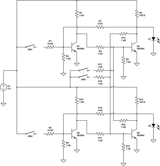
Take the top half for explanation.

If SW3 is closed (reset), Q2 is on, so Q1 is off. LED is off. There is no drive to R15. Release SW3.

If SW1 is closed, Q1 is turned on, so Q2 turn off. LED comes on, and R7 turns on Q1, latching the condition. Also, R15 turns off Q4, preventing any operation of the lower section.

R6 is sized at 330 ohms to allow ~10 mA to the LED. If you want more LED drive you can reduce R6. If you do, you may need to reduce R3 and R4, which are sized to give 2 mA base drive to Q2, and you may need to reduce R7. If you try to use a high-brightness LED, with a 4-volt forward drop, you may need to reduce R6 by a lot, and going to a higher supply voltage may be a good idea.

And once again - you made "minor modifications" to Dave Tweed's circuit which included changing resistors to diodes. Then you asked for help in reducing the number of diodes you needed. Do you really not see a problem with your thinking?

WhatRoughBeast
  • 59,978
  • 2
  • 37
  • 97
  • Ok, I will follow your advice. I just want to tell you it's the same as Dave tweed's circuit with minor modifications. – Kartik Jul 28 '14 at 07:12
  • I'm going to have to change my answer. As per Dave Tweed's original answer, you don't need diodes at all. – WhatRoughBeast Jul 28 '14 at 13:19