(1) Processor pin or similar drive
If a processor or other device was available with enough current drive and a rail to rail square wave (which some 6th sense [tm] suggests to me may be the case in this case) then a simple diode pump from a single pin may suffice. This could be driven from any point with a rail to rail rectangular wave present with a suitable mark space ratio range plus drive capability as above.
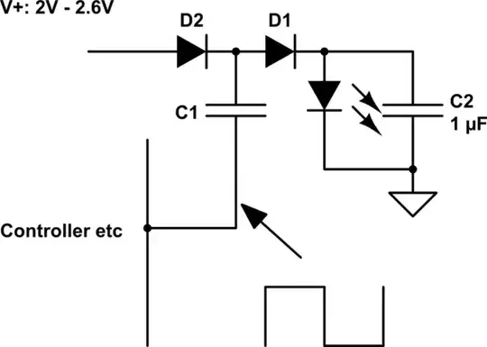
simulate this circuit – Schematic created using CircuitLab
VLED max ~+ 2 x V+ - 2 x Vdiode_drop.
At V+ = 2V, VLED max = 2 x 2 - 2 x 0.3 = 3.4V.
Many modern White LEDs could be operated from this voltage.
As an indication of what could be achieved, an LED rated at say 150 lumen/Watt and with 1 mA LED current would make about 3V x 0.001A x 150 lumen/Watt ~= 0.5 lumen.
If this light was distributed evenly over an A4 sheet (hard to do evenly) then light level = 0.5 Lumen (0.21 m x 0.3m) = 8 lux.
At 2.5 mA LED current illumination level rises to 20 lux over an A4 sheet and text and colour pictures would be easily read by most (despite what many text books say.)
LED current can come in pulses as long as the frequency was high enough to avoid LED flicker and as long as peaks of capacitor discharge current does not over-stress the LED.
(2) Asian (or other) IC.
This circuit meets your spec rather well.
The main qualification is availability of the IC in Western markets.
The IC is available as a
QX5252F (TO94 pkg (similar to TO92 but with 4 leads)) and
QX5252E in a DIP pkg.
The 5252x operates from a single NimH or NiCd cell and the 5253x is the same but operates from 2 cells. The latter would be best suited to your spec.
The DIP version adds variable light level sensitivity when used as a solar lamp controller.
The IC costs around 10 cents in modest volume in China and probably a few tens of cents in 1's.
Features include
LED driver.
Brightness level set by inductor value
Internal PV isolation diode and switch MOSFET so ...
Total circuit comprises IC, LED, inductor, battery.
The IC goes into shutdown mode when Vin is above a preset voltage and drives the LED when Vin is below a preset level. This feature is used to provide auto turn-on turn=-off lawn light control. SBAT can instead be used as an enable line or tied low for permanent operation.
From memory efficiency is in the 85% region -= better than many informal circuits.
(3) From the archives ...
from this stack exchange question is a good start.
This circuit will flash an LED of any colour and forward voltage (or potentially even several LEDs in series) or will pulse a load using one cell - probably about 1 volt will be enough to operate it. I "designed" this circuit but it is based on a design that has not only long been used in transistor form but existed in pre-transistor thermionic valve days and, while I have never seen it used elsewhere, I would be surprised if it has not been independently "developed" by many other people.
As shown Q1 collector is driven negative below ground when Q1 turns off until energy in L1 is dissipated. Swap ground and supply and transistor types for +ve supply.
Add diode from output to use as a DC supply.
L1 - small potted "resistor like" inductor or many others - experiment.
Q1 Q2 - almost any "jellybean" small pnp & npn transistors.
C1 polarised only to get high capacitance per size.
Can be eg ceramic if capacitance high enough for needs.
Use only either LED2 (best) or LED1 at one time.
Use either LED2 (most efficient) or LED1
Time constant ~= R2 x C1.
Long time constant leads to discrete flashes.
Short time constant produce apparently permanently on LED.
Use resistor between Q1b-Q2c for higher supply voltages.
Resistor in series with C1 will extend pulse length.
More soon ...