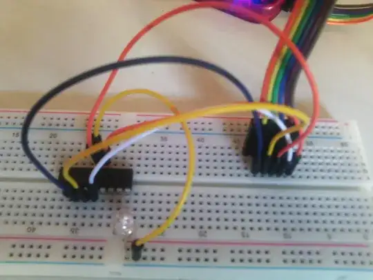
I want to blink LED with PIC16F628A and run it directly with the button make and program device main project of MPLAB X. to programing the PIC I did simple wiring shown in this tutorial without using any resistor (just wiring).
To blinking the LED I just wired RA0 ---> resistor ---> LED ---> ground but nothing works.
Should I remove some wires after programming the PIC or add something?
code :
#include<htc.h>
#include <pic.h>
#include <pic16f628a.h>
// Config word
__CONFIG(FOSC_INTOSCIO & WDTE_OFF & PWRTE_ON & CP_OFF);
#define LED  RA0
#define _XTAL_FREQ   4000000
void main()
{
        TRISA0 = 0;                // Make RA0 pin output
        LED    = 0;
        CMCON = 0x07;
        // Make RA0 low
    while(1)
    {
        __delay_ms(1000);       // Half sec delay
        LED = 0;               // LED off
        __delay_ms(1000);       // Half sec delay
        LED = 1;               // LED on
    }
}
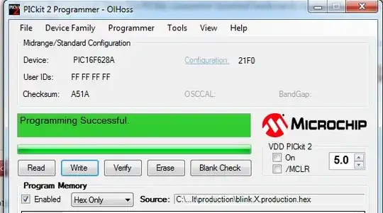
MPLAB X output
BUILD SUCCESSFUL (total time: 5s)
Loading code from C:/Users/makhlouf/MPLABXProjects/blink.X/dist/default/production/blink.X.production.hex...
Loading completed
Connecting to programmer...
Programming target...
Programming completed
Running target...