I have written and using a STM32F030F4 for toggle a pin. I configured all things and my program is this (I use GPIOA->ODR ^= GPIO_PIN_2 for toggle GPIOA2 in Infinite loop ):
#include "stm32f0xx_hal.h"
/* Private variables ---------------------------------------------------------*/
/* USER CODE BEGIN 0 */
/* USER CODE END 0 */
/* Private function prototypes -----------------------------------------------*/
void SystemClock_Config(void);
static void MX_GPIO_Init(void);
int main(void)
{
/* USER CODE BEGIN 1 */
/* USER CODE END 1 */
/* MCU Configuration----------------------------------------------------------*/
/* Reset of all peripherals, Initializes the Flash interface and the Systick. */
HAL_Init();
/* Configure the system clock */
SystemClock_Config();
/* System interrupt init*/
HAL_NVIC_SetPriority(SysTick_IRQn, 0, 0);
/* Initialize all configured peripherals */
MX_GPIO_Init();
/* USER CODE BEGIN 2 */
/* USER CODE END 2 */
/* USER CODE BEGIN 3 */
/* Infinite loop */
while (1)
{
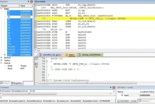
GPIOA->ODR ^= GPIO_PIN_2; //toggle GPIOA2
}
/* USER CODE END 3 */
}
/** System Clock Configuration
*/
void SystemClock_Config(void)
{
RCC_ClkInitTypeDef RCC_ClkInitStruct;
RCC_OscInitTypeDef RCC_OscInitStruct;
RCC_OscInitStruct.OscillatorType = RCC_OSCILLATORTYPE_HSE;
RCC_OscInitStruct.HSEState = RCC_HSE_ON;
RCC_OscInitStruct.PLL.PLLState = RCC_PLL_ON;
RCC_OscInitStruct.PLL.PLLSource = RCC_PLLSOURCE_HSE;
RCC_OscInitStruct.PLL.PLLMUL = RCC_PLL_MUL6;
RCC_OscInitStruct.PLL.PREDIV = RCC_PREDIV_DIV1;
HAL_RCC_OscConfig(&RCC_OscInitStruct);
RCC_ClkInitStruct.ClockType = RCC_CLOCKTYPE_SYSCLK;
RCC_ClkInitStruct.SYSCLKSource = RCC_SYSCLKSOURCE_PLLCLK;
RCC_ClkInitStruct.AHBCLKDivider = RCC_SYSCLK_DIV1;
RCC_ClkInitStruct.APB1CLKDivider = RCC_HCLK_DIV1;
HAL_RCC_ClockConfig(&RCC_ClkInitStruct, FLASH_LATENCY_1);
__SYSCFG_CLK_ENABLE();
}
/** Configure pins as
* Analog
* Input
* Output
* EVENT_OUT
* EXTI
*/
void MX_GPIO_Init(void)
{
GPIO_InitTypeDef GPIO_InitStruct;
/* GPIO Ports Clock Enable */
__GPIOF_CLK_ENABLE();
__GPIOA_CLK_ENABLE();
/*Configure GPIO pin : PA2 */
GPIO_InitStruct.Pin = GPIO_PIN_2;
GPIO_InitStruct.Mode = GPIO_MODE_OUTPUT_PP;
GPIO_InitStruct.Pull = GPIO_NOPULL;
GPIO_InitStruct.Speed = GPIO_SPEED_HIGH;
HAL_GPIO_Init(GPIOA, &GPIO_InitStruct);
}
As reference manual has said:
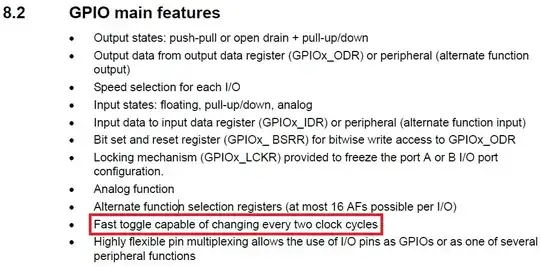
Thus if 2*2=4 that mean each 4 cycle make a toggle in GPIOA2. then frequency ought to be 48/4=12MHz (48 is MCU clock because as you can see in codes I have used PLL and I have multiplied 8MHz to 6). is it correct?
let to impelement the code on MCU. look at my saleae result:
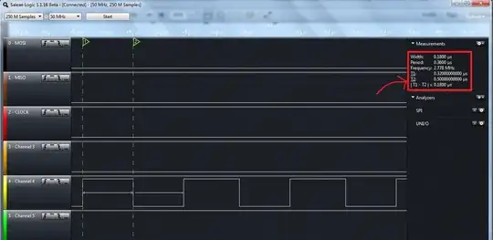
Huh!!!?? is the output frequency correct? is there any point?
Edit:
The assembly for the toggle is this: