3

I'm working on a power supply build and need a dummy load. I've found many mentions here that are good for a few amps, but I need one that's good for 30A or more... at 5V. I thought about just using some high wattage LEDs or something but they all require 30V or more. Being variable isn't a hard requirement but would be nice. I want to be able to ramp up the current draw until I hit my limiter so I can test it actually works. If it jumps straight to the limit, that doesn't really help.

Any suggestions?

Adam Haile
  • 1,603
  • 5
  • 31
  • 50
  • BJT with a large value pot across emitter and collector, the wiper to the gate and a huge heat-sink? Or do you want to regulate the current? As with a constant current load. – Evan Jul 17 '14 at 18:59
  • 3
    1 ohm 25W resistor on suitable heatsink will take 5A. Repeat 6 times... –  Jul 17 '14 at 19:04
  • Can't you test the current limit with a dead short? I've heard some audio types test their amps with a coil of nichrome wire in bucket of oil. – George Herold Jul 17 '14 at 19:46
  • Could I just test it with a big rheostat like [this](http://www.ebay.com/itm/200W-5-OHM-High-Power-Wirewound-Potentiometer-Rheostat-Variable-Resistor-/130697179186?pt=Vintage_Electronics_R2&hash=item1e6e28b032)? At its max resistance I'd get 1A and I could keep dialing it down util I'm using around 25A @ 0.2 ohm... – Adam Haile Jul 17 '14 at 19:59
  • If you find you're doing this a lot, save yourself some grief and buy an electronic load. – Spehro Pefhany Jul 17 '14 at 20:01
  • What's really the difference? My voltage source is constant... so I just need to vary the resistance, right? – Adam Haile Jul 17 '14 at 20:04
  • @AdamHaile - If you pay attention to the rheostat data sheet, you'll notice the 6.3 amp limit. This is due both to the power dissipated and the current capacity of the sliding contact of the wiper. If you try to crank down the wiper you get two effects - the wiper current goes up, and the active section of the rheostat gets proportionally hotter (more power in a smaller region). Neither is good. – WhatRoughBeast Jul 17 '14 at 21:27
  • Yeah... I just noticed that. So maybe a bigger rheostat? :P – Adam Haile Jul 17 '14 at 21:28
  • Right - "When all else fails, get a bigger hammer". I think you'd be better off with my power resistor approach. Probably cheaper, too. – WhatRoughBeast Jul 18 '14 at 12:21

4 Answers4

2

Another approach is to say to Hell with elegance and just brute-force it. Get a bunch of power resistors and hook them up. For instance, DigiKey will sell you 5-ohm, 10-watt resistors for about $1.60 each. Each resistor will draw 1 amp at 5 volts, and 30 of them will cost about $50. Set up an array with some way to connect them independently and you can provide your load in steps of 1 amp, which I'd guess is fine enough resolution for your purposes. It's crude, but probably quicker than messing around with transistors and heatsinks and all that.

WhatRoughBeast
  • 59,978
  • 2
  • 37
  • 97
0

Try this, if you like

schematic

simulate this circuit – Schematic created using CircuitLab

The transistors are any medium-to-high power NPN transistors. The 12 volt supply should be capable of about 2 amps (at a guess). The transistors MUST be mounted to a pretty good heat sink, since the may be called upon to dissipate more than 50 watts. The .5 ohm resistors must also be big, like 50 watts each, and care taken to cool them. If you like, you can reduce the value of the emitter resistors to cut their dissipation, but then the control voltage supplied by the pot becomes more sensitive, and the total dissipation of the transistors increases.

WhatRoughBeast
  • 59,978
  • 2
  • 37
  • 97
0

You'll definitely need a large heatsink and maybe a fan system. 30A at 5V is 150 watts and a resistance of 0.167 ohms. If you intend to soak it for minutes or hours then fans are a good idea but you'll still need a heatsink to take power away from the candidate silicon that does the business end of taking the current. Here's a circuit idea: -

enter image description here

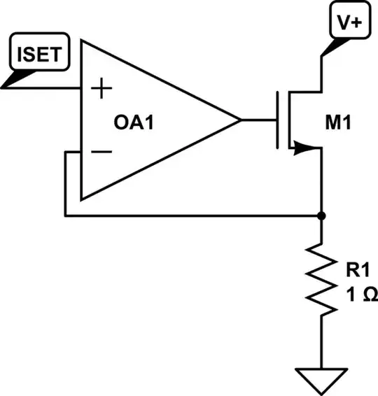
Bear in mind that this circuit is just the basics. It shows an N channel mosfet driven from an op-amp and there is feedback from a 1 ohm resistor. Basically "Iset" is a voltage demand (lets call it 1 volt and the op-amp tries to get both it's inputs at 1 volt because of negative feedback - this means there has to be 1 volt across R1 and hence there will be 1 amp flowing thru R1.

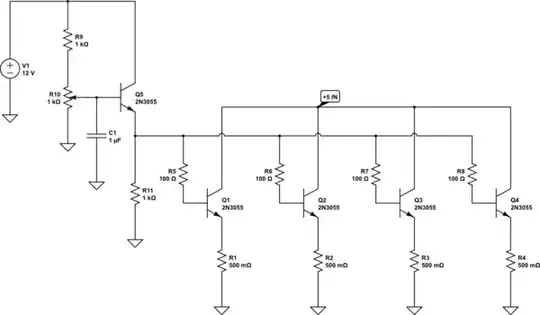
The difficulties start now - you need a resistor that is more like 0.01 ohms and it will have a power dissipation of 30 amps squared * 0.01 ohms = 9 watt - maybe you can find a 1 milliohm resistor but wiring sense wires to it is always problematic and you'll have to pick the right resistor or you could easily be interpreting 30 amps as 20 amps of 40 amps. The next difficulty is finding a MOSFET that can do the job of shunting the power supply to a resistance of about 0.16 ohms when there is only 5 volts available to drive the gate - you could use a Traco power inverter to give you an op-amp supply of 12V of course but don't underestimate the picking of the MOSFET - in fact I might suggest you need to pick several, all running in parallel from their own respective op-amp thus sharing the current. You can then mount them on a large heatsink and get ready to turn the fans on.

Andy aka
  • 434,556
  • 28
  • 351
  • 777
-1

All too complicated. A simple circuit is all that is needed. Example: 28v supply for a load of 30 amps needs only a .93K resistor with a lamp in parallel, and in series with a normally open contact switch. When the switch is closed you should have instant brightness of the lamp or if you prefer use a amp meter in series with the resistor. Caution!! The resistor will get very hot quickly. This simple circuit is for a "instant" proof of maximum current.