9

Here is a 32 MHz crystal from one of TI's reference design

enter image description here

The BOM list defines the crystal as

" CRYSTAL, OSCILATOR, 32MHz, 10pF, 10PPM/+10PPM, ‐40DEGC/+85DEGC, SMD"

It is for a MCU (ARM M3) and the datasheet has this sub-chapter:

enter image description here

Here is the link to 32 MHz Crystal Oscillator chapter:

enter image description here

When I use the above CL formula:

CL = 1 / (1/12pF + 1/12pF) + Cp = 6 pF + Cp

Another reference design of TI that uses a chip from the same family has the below crystal enter image description here

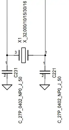
all the other definations are the same as above formulas and notes. The BOM defines the crystal as:

Crystal, 32.000MHz, NX3225DA, 10/15ppm, 16 pF ! Temp range -30 - +85 deg C !

CL = 1 / (1/27pF + 1/27pF ) + Cp = 13.5pF + Cp

I could not really understand how C341 and C351 values are chosen, could anyone please explain it?

And How do you assume Cp's value?

sven
  • 718
  • 2
  • 10
  • 28

1 Answers1

6

Cp is the input capacitance plus stray capacitance. You can use a few pF (3-5pF) for the value unless something is really strange.

So, for a crystal rated with a 10pF load, Cl = (10pF-Cp)\$\cdot\$2, so if we use 4pF for Cp, we get 12pF for the load capacitors.

For the 16pF crystal, Cl = (16-Cp)\$\cdot\$2, so using 4pF for Cp we get 24pF, using 3pF we get 26pF.

Spehro Pefhany
  • 376,485
  • 21
  • 320
  • 842
  • Thank you for the explanation. I have another question. Is the second one a bad example as it refers the maximum suggested capacitance load instead of typical? Is the frequency becomes unstable if only C341 or C351 is used? why it is not preferred to use only one cap that would save some space on the board and couple cent – sven Jul 17 '14 at 14:59
  • I suppose they consider that range of capacitor specification to be acceptable for the purposes of the EVM clock **with the specified load capacitors**. You do need both capacitors for the Pierce oscillator to work reliably. – Spehro Pefhany Jul 17 '14 at 15:04