12

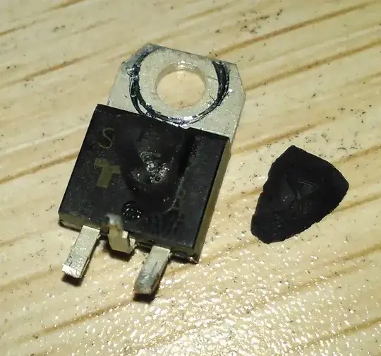
Some of our boards have a damaged SCR. I just witnessed one in person today. The SCR actually exploded upon power-on. A part of its packaging material just flew off along with an exploding sound. The resulting dead body of the SCR is shown here:

SCR in Pieces

I have a few questions about the circuit:

Schematic

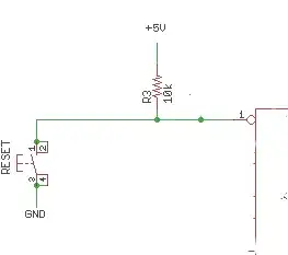
Q1 (S6020L) is the SCR in question. It is rated 600V, 20A. AC input is 220V. What I did is:

  1. Remove AC/Power off.
  2. Discharge C5
  3. Power on. At the very same moment, Q1 exploded in pieces.

If the SCR is turned on when the rectified AC signal is right near its peak and the voltage at C5 is close to zero, I would imagine there is a huge inrush current to charge up the big capacitor.

The questions I am having are:

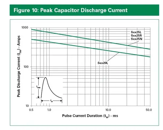
  1. How do I calculate the magnitude and duration of this inrush current.
  2. Does this inrush current exceed the specification of this particular SCR?

The rectifying bridge, GBJ2006, is not damaged in this case.

We have produced and sold a few hundred boards. There have been some occurrences of this problem. I am wondering if we should somehow change the design (I am not a hardware guy).

The SCR in question is not really from Littelfuse, but it matches S6020L in specification, as I heard from our hardware designer. I have no idea what manufacturer it is from and trying to determine if it is a design issue or a part quality problem.

The MCU (not in the schematics attached) sees the SYNC signal and triggers the SCR at appropriate times to ramp up the voltage at C5. This way the inrush current would be reduced considerably. The problem is that before my software takes charge, there may a glitch that triggers MOC3052M upon power-on. This is a one time thing and after that the software takes full control. I am having the doubt about the quality of the SCR part because this inrush current is not repetitive. The moment I witnessed the SCR explosion is without any load and right at the switch-on of the power switch. I know the obvious solution is to get rid of the glitch; however, I just want to know if this part is faulty.

HV_Bus (C5) is connected to a 1.25-HP motor, whose other terminal is connected to a MOSFET. MCU will turn on and off the MOSFET with a PWM signal and C5 gets discharged with this load. When the PWM signal is active, MCU triggers the SCR with a 2kHz frequency and keeps C5 charged.


AC mains hazards:

enter image description here

Russell McMahon
  • 147,325
  • 18
  • 210
  • 386
Brian Wang
  • 413
  • 2
  • 6
  • 16
  • 7
    That "LUG3 NC GND" worries me... –  Jul 17 '14 at 13:30
  • How did you discharge C5? – sherrellbc Jul 17 '14 at 13:31
  • 4
    +1 nice photo and nicely asked question. Be careful with that circuit, C5 can kill you. – Vladimir Cravero Jul 17 '14 at 13:32
  • 5
    calling any part of that circuit GND is troubling. – markrages Jul 17 '14 at 13:33
  • can you guys elaborate the problem with ground? I am sure that's something big but I'm missing it. – Vladimir Cravero Jul 17 '14 at 13:34
  • 8
    The "ground problem" is that if that lug were ever to be actually connected to the AC system ground, you would blow up your bridge rectifier. Keep in mind that AC neutral is bonded to AC ground. This shorts out one of the diodes in the bridge rectifier, and puts full line voltage across one of the others, which will immediately fail. This really a criminally negligent design. The negative terminal of the bridge rectifier -- and all other points currently labeled "Gnd" -- MUST BE ISOLATED from any real ground at all costs. – Dave Tweed Jul 17 '14 at 14:32
  • @DaveTweed I understood this, I did not see the connection with the SCR though. – Vladimir Cravero Jul 17 '14 at 15:10
  • The additions re one time event, normally mains cycle synchronised triggering and start up spike would have greatly aided giving a good answer initially. My zero crossing opto solution would fix that but allow only half cycle long charging period increments. A startup lockout on the SCR would be "easy". | Fig 6-23 says allowable cycle surge current for the genuine part is about 300A or about 200A max for 0.1s | It comes down to "what voltage can you achieve if you connect peak mains to a discharged 560 uF cap via the cct shown. I wiring plus R_T2_choke > about 1 Ohm you SHOULD be OK. – Russell McMahon Jul 18 '14 at 03:50
  • Thank you all for the heads-up on the ground. I know the danger of connecting the GND to the AC ground since I have seen one... It was actually very scary due to the explosion, especially to a software guy... – Brian Wang Jul 18 '14 at 08:39

5 Answers5

9

The only sure limitation of the current is your common-mode choke and your internal wiring.

The S6020L (if your SCR really matches the specifications) is capable of a one-time pulse of 0.01second and 255A at room temperature. So if your wiring + CM choke is less than around an ohm (and it will not be), there is no guarantee you won't exceed the maximum specifications (and it should be noted that you really should stay reasonably far away from these one-time pulse at room temperature limits- it may be hotter than room temperature and repetitive surges may kill the SCR eventually).

enter image description here

Since you have a sync signal, and presumably a processor reading that, I think the best solution might be a firmware change that triggers the SCR only at the zero crossing. The current would then be limited by the dv/dt of the mains line at the zero crossing. At 220V RMS, and \$\omega\$ = 2\$\pi\$50 = about 0.1V/usec, so the current will be limited to 56A, well within specifications.

Failing that, perhaps you could change the opto-triac for one that has built-in zero crossing detection (eg. MOC3063), but I have not looked carefully to see if that will work with your diode setup- you may need to put a resistor across C1, for example.

Spehro Pefhany
  • 376,485
  • 21
  • 320
  • 842
  • What have I missed (something it seems). If you trigger the SCR at zero crossing does it not just pick up the load as Vmains exceeds Vcap? – Russell McMahon Jul 17 '14 at 14:51
  • 1
    @RussellMcMahon The current is limited by the dv/dt of the sinusoidal mains, i = C*dv/dt, so if you differentiate 220*sqrt(2)*sin(w*t) you get a maximum of 2*pi*50*220*sqrt(2) volts/second (max at the zero cross since cos(0) =1). Only about 100,000 volts/second. – Spehro Pefhany Jul 17 '14 at 14:59
  • @SpehroPefhany You are sharp. I do control the SCR based on the SYNC signal. However, there may be a glitch before my software takes control. I added the description in my question. This is really a one-time surge. Should this kill the SCR? – Brian Wang Jul 18 '14 at 00:51
  • Yes it's quite possible for a one- time event to kill the SCR, depending on exactly when it is triggered and what the power source impedance is like. – Spehro Pefhany Jul 18 '14 at 00:59
  • @SpehroPefhany - You seem to be agreeing with me. Yes? ie zero crossing removes the problem. The OP now notes that he is "usually" doing ZC but maybe not always. If he'd said that then my ZC answer would still be right but the non ZC spike would explain what's happening. – Russell McMahon Jul 18 '14 at 03:33
  • @RussellMcMahon. Yes, I agree with that! – Spehro Pefhany Jul 18 '14 at 04:00
  • @SpehroPefhany Thanks. The consensus is to avoid the high inrush current wherever possible. Even if the SCR part is very durable, it is always a good idea not to put it under such harsh condition, not even once. :-) – Brian Wang Jul 18 '14 at 08:43
7

You probably need a zero-crossing trigger for the SCR

The MOC3052 is non zero crossing and you can trigger it anywhere in the mains cycle. Do so near cycle peak with a discharged cap and you expect to get what you are getting.

You can get zero crossing isolators in the same series that are a drop in replacement for the MOC3052.

eg The MOC3063 seems more than adequate - 600V Vmax (same as MOC3052) and 5 mA maq trigger current against 10 mA. A closer match will be able to be found if desired.

If you trigger the SCR at zero crossing the SCR will forward conduct when V_DC_Rectified exceeds V_C5 and have zero initial inrush current.

D1 is probably not needed.
IF I was actually implementing this I'd pore over the relevant data sheets to ensure that all polarities and voltages were OK at all times BUT it seems OK at a glance.

Russell McMahon
  • 147,325
  • 18
  • 210
  • 386
  • Is there a tutorial on zero-crossing photo triac? I could not find a good reference on how it works, probably because I am not good at hardware. I assume that if MOC3063 is used in place of MOC3052 here, the SCR will only be triggered right after zero crossings. Therefore, C5 will only see a voltage slightly higher than itself and charge up more slowly, effectively reducing the inrush current. The side effect is that I cannot trigger the SCR at will. Please correct me if I am wrong. I am terrible at hardware. Thanks in advance. – Brian Wang Jul 18 '14 at 09:00
3

It sounds like you've analyzed the problem well. You've got a device that's pretty clearly failing due to being overheated, and the only obvious path for current to flow through the SCR is from the rectifier into C5.

You've got a couple options. One is to use a bigger SCR, like you suggest. Unfortunately, the current through in the SCR in that case is going to be difficult to predict, because you don't know the impedance of your source.

As a deeper question, though, I'm not sure what that SCR is doing in this circuit. It looks like it might be intended as a precharge, but there's no actual precharge path. A better option may be to put a resistor around that SCR, and delay firing it for some period after start-up. You just need to delay by maybe three time constants (R of your new resistor times 560 uF), so if you know what the firing delay of your existing circuit is, you can pick R appropriately.

Stephen Collings
  • 17,373
  • 17
  • 92
  • 180
  • Agreed. I have seen the parallel resistor help precharge C5. Another option is to use a PTH resetable fuse in series with the SCR to protect it on power up. – Whistle1560 Jul 18 '14 at 01:59
0

I believe that the problem is that you are applying a "non-isolated" ground to the bottom lead of the SCR, applying the full voltage across the SCR, causing a huge current to flow through it, causing it to overheat and explode! Most likely it's the motor that is not isolated, the hot and neutral reversed, etc.

Guill
  • 2,430
  • 10
  • 6
0

The problem is C1, when the system is turned on, C1 gives "+" voltage to the gate for a while, when the anode is tied to VCC and C5 is initially short circuited, the cathode is grounded, so that´s why the SCR explodes, I suggest to eliminate C1.

Greenonline
  • 2,064
  • 7
  • 23
  • 38
RODFER
  • 1