10

I have a ton of 2N3904 transistors and would like to use them for my RTL logic project. Based on what I could figure out on the web, and the parts I had, I've gotten logic gates to work quite well with the following values:

schematic

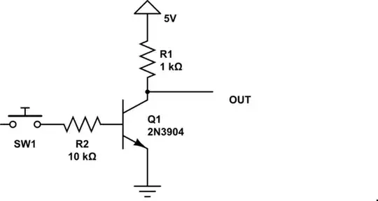
simulate this circuit – Schematic created using CircuitLab

Although this works fine, I'm a bit concerned about what I've read on the data sheet for the 2N3904. It states that the Base-Emitter Saturation Voltage has the following specs:

Ic = 10mA Ib = 1.0mA Ic = 50mA Ib = 5.0mA

I'm having a hard time understanding what that means exactly. If you calculate the current for the base input with Ohm's Law, we get I = 5 / 10000 = 0.0005. Am I correct that this is 5mA? I replaced R2 with a 5K resistor and it switched the same, which would be 0.001 or 10mA.

Like I said, it is working at the moment. I just want to make sure that I purchase the right resistors for the job. I know that the goal is for the transistor to be fully saturated, however I don't know if this is how that is done or not.

Thanks,

Transistor
  • 168,990
  • 12
  • 186
  • 385
JohnnyStarr
  • 675
  • 2
  • 7
  • 18
  • wouldn't one miliAmp be 1/1000A or 1e-3A? If so, then it is not 10mA as you have write, but 1mA. and also is not 5mA but 0,5mA or 500uA. agree? – Cristiano Dec 18 '16 at 16:51

1 Answers1

18

Every transistor has a current gain, usually \$\beta\$ or \$h_{fe}\$ in the datasheet. Typical values are on the order of 100. When the transistor is not saturated, then the base current and collector current are related by this factor:

$$ I_c = h_{fe} I_b $$

When the base current increases to the point where collector current can increase no more, the transistor is said to be saturated. The collector current can increase no more because it can't permit any more current -- the current is entirely limited by R1 in your diagram, and the voltage from emitter to collector is at a minimum.

When we design digital logic, we don't want to just barely saturate the transistors. We want to saturate them a lot. This provides some extra margin against variations in \$h_{fe}\$, and also takes into account that for higher frequencies (necessary for quick high/low transitions), \$h_{fe}\$ is effectively reduced.

Rule of thumb: in digital logic, design for a collector current 15 times greater than the base current.

So here, you've selected a collector resistor of 1kΩ. At saturation, the emitter-collector voltage is much less than the supply voltage, so we can estimate the collector current as:

$$ I_c = \frac{5\mathrm V}{1\mathrm k\Omega} = 5\mathrm{mA} $$

We want the base current to be 1/15th that (0.33mA), and the voltage across the base resistor will be the supply voltage, less about 0.65V from the base-emitter junction of Q1. So:

$$ R_2 = \frac{5\mathrm V - 0.65 \mathrm V}{0.33\mathrm{mA}} = 13 \mathrm k \Omega $$

Your selection of 10kΩ is close enough.

You can also scale the resistor values up, maintaining the ratio of base to collector current, but reducing the current overall. That reduces your power consumption, but also reduces the logic speed as the smaller currents are able to charge the parasitic capacitances less rapidly. This is a performance vs. power consumption trade-off that you get to make as the engineer.

Phil Frost
  • 56,804
  • 17
  • 141
  • 262
  • 1
    So, the ability to fully saturate the transistor is based more on the ratio of collector/base currents, than it would be the actual values of the transistor? In other words, I could probably use several kinds of transistors with a 1K (collector) 13K (base) ratio? – JohnnyStarr Jul 11 '14 at 21:04
  • 1
    How does this approach guarantee the transistor will be in saturation if you are designing only for a gain of 15? – sherrellbc Jul 12 '14 at 00:39
  • 1
    @sherrellbc because the gain of any transistor you are likely to use will have a gain of *much more* than 15. – Phil Frost Jul 12 '14 at 00:40
  • 1
    @JohnnyStarr it does depend on the gain of the transistor, but a typical, general-purpose, small-signal BJT (like 2N3904, BC547, 2N2222, etc.) will have a current gain on the order of 100. It actually varies by a wide margin even between specimens of the same part number, so the approach is to anticipate a gain that is surely less than the gain you will get so that you don't even run into a problem where your logic doesn't saturate the transistor. – Phil Frost Jul 12 '14 at 00:43
  • 1
    So then since the gain is likely much higher you would expect the transistor to saturate far earlier than with a base current of 330uA? The idea seems solid but that base current seems really small. If we are assuming the transistor *can* saturate at 1mA collector current then a rough estimate would but the associated base current at 10uA (~gain of 100)? And since we are designing for 330uA base current, saturation is guaranteed. – sherrellbc Jul 12 '14 at 00:44
  • 1
    @sherrellbc Yes, the transistor probably will saturate at some base current below 330μA. We provide more base current than necessary to be really sure. Also keep in mind, the collector current at saturation depends on the load (R1 here), not the transistor. The saturation collector current in this example will always be approximately 5mA as long as R1=1k and Vcc=5V, regardless of what transistor we put there. – Phil Frost Jul 12 '14 at 00:53
  • Thank you. The theory makes sense, I guess I have not had enough experience with transistors to have come across one at any point that saturates at ~10uA. Of course it's possible, it just seems that 10uA is nearly on the borderline of being a product of noise in your system. Then again, it was designed this way to saturate at such low inputs. – sherrellbc Jul 12 '14 at 00:55
  • 1
    @Phil Frost you mentioned that my 'selection of 10kΩ is close enough', although 13K would be 1 1/15 of the collector current. Will this still be close enough on a very large scale, such as a CPU that uses over 2000 transistors? It seems, that using a lower value resistor, it might actually ensure that the voltage level doesn't drop too low on a complex circuit. Of course, this may just be an assumption. If that is the case, wouldn't 10K be ideal? – JohnnyStarr Jul 14 '14 at 15:36
  • 1
    @JohnnyStarr A cpu that uses 2000 transistors probably won't use RTL. Consider with just this one transistor, you have 5mA through 1kΩ for a power of \$(5mA)^2 = 1k\Omega = 0.025W\$. Multiplied by 2000 transistors, that's 50W. Pretty toasty. Anyway, the "15" rule of thumb is to leave a wide margin for variation, so if the base resistor varies by 30%, that's not a big deal. Making the base resistor smaller just means more base current, so you are even more sure the transistor is driven to saturation. So, even more margin -- extra safe, at the expense of higher power. – Phil Frost Jul 14 '14 at 16:10
  • 1
    @Phil Frost Thank you Phil! And yes, 50W is kinda crazy, but so am I. I am building a 4-bit CPU using RTL and breadboards. Its partially for learning, but also just a great challenge. – JohnnyStarr Jul 15 '14 at 17:25
  • 1
    @JohnnyStarr For that project I'd use discrete MOSFETs like 2n7000. The cost is similar, and the logic can be essentially the same, except you can make the quiescent currents lower and you don't need a base resistor on each transistor. – Phil Frost Jul 15 '14 at 17:32
  • 1
    @Phil Frost That is fascinating. Could I use the same 5V supply with 1K to the collector (or I think its 'source' on mosfets)? Would this provide faster switching as well? – JohnnyStarr Jul 16 '14 at 18:33
  • 1
    @JohnnyStarr yes, you could use the same power supply. Considering just transistors themselves, BJTs are inherently faster that MOSFETs, but in your project I bet the maximum speed will be limited by the breadboards due to the huge inductance and capacitance they add. You will to a point, increase speed at the cost of power by reducing the collector resistor (which otherwise limits the rate at which you can charge the gates of the next transistor), until the inductance of the breadboard or your ability to not melt the circuit becomes the limiting factor. – Phil Frost Jul 16 '14 at 18:38
  • 1
    @Phil Frost Wow, I didn't realize the breadboards would cause that much of an issue. I may need to solder this project after all. – JohnnyStarr Jul 16 '14 at 18:43
  • 1
    @Phil Frost I also meant to ask, how slow are we talking here? What methods can I use to determine how fast/slow the circuit will be without melting my breadboards? I suppose any speed around 1 to 10KHz would be neat. Or, are you suggesting that it would be much slower, around 50Hz or so? – JohnnyStarr Jul 16 '14 at 19:35
  • 1
    @JohnnyStarr 10KHz is easy peasy, just about any way you slice it. – Phil Frost Jul 16 '14 at 20:39
  • @Phil Frost My main concern is the circuit not catching on fire or something terrible. Is there a formula to calculate how fast it will clock? Or, is it a situation where I have to get an oscilloscope and bump up the speed as I go? If 10KHz is easy, what do you estimate being too high? – JohnnyStarr Jul 16 '14 at 20:50
  • @JohnnyStarr I'd suggest [asking more questions](http://electronics.stackexchange.com/questions/ask). – Phil Frost Jul 16 '14 at 21:31