I have written a program in Keil that blinks a LED via External GPIO Interrupt. Here is how I have configured it in STM32CubeMX:
At first, I enabled and configured RCC as you can see and configured PA0 for external interrupt and PB1 as output.
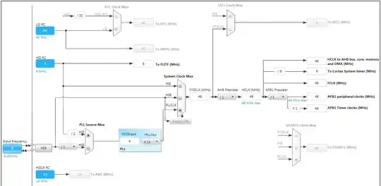
For clock source, I configured it as you can see below.
And for Pins

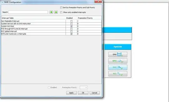
I checked the "EXTI Line 0 and Line 1 interrupt" checkbox. I'm not sure that checking this checkbox is necessary.
After configuration, I generated the source code below (main.c):
/* Includes ------------------------------------------------------------------*/
#include "stm32f0xx_hal.h"

/* Private variables ---------------------------------------------------------*/

/* USER CODE BEGIN 0 */

/* USER CODE END 0 */

/* Private function prototypes -----------------------------------------------*/
void SystemClock_Config(void);
static void MX_GPIO_Init(void);

int main(void)
{

  /* USER CODE BEGIN 1 */

  /* USER CODE END 1 */

  /* MCU Configuration----------------------------------------------------------*/

  /* Reset of all peripherals, Initializes the Flash interface and the Systick. */
  HAL_Init();

  /* Configure the system clock */
  SystemClock_Config();

  /* System interrupt init*/
  HAL_NVIC_SetPriority(SysTick_IRQn, 0, 0);

  /* Initialize all configured peripherals */
  MX_GPIO_Init();

  /* USER CODE BEGIN 2 */

  /* USER CODE END 2 */

  /* USER CODE BEGIN 3 */
  /* Infinite loop */
  while (1)
  {

  }
  /* USER CODE END 3 */

}

/** System Clock Configuration
*/
void SystemClock_Config(void)
{

  RCC_ClkInitTypeDef RCC_ClkInitStruct;
  RCC_OscInitTypeDef RCC_OscInitStruct;

  RCC_OscInitStruct.OscillatorType = RCC_OSCILLATORTYPE_HSI;
  RCC_OscInitStruct.HSIState = RCC_HSI_ON;
  RCC_OscInitStruct.HSICalibrationValue = 16;
  RCC_OscInitStruct.PLL.PLLState = RCC_PLL_ON;
  RCC_OscInitStruct.PLL.PLLSource = RCC_PLLSOURCE_HSI;
  RCC_OscInitStruct.PLL.PLLMUL = RCC_PLL_MUL12;
  RCC_OscInitStruct.PLL.PREDIV = RCC_PREDIV_DIV1;
  HAL_RCC_OscConfig(&RCC_OscInitStruct);

  RCC_ClkInitStruct.ClockType = RCC_CLOCKTYPE_SYSCLK;
  RCC_ClkInitStruct.SYSCLKSource = RCC_SYSCLKSOURCE_PLLCLK;
  RCC_ClkInitStruct.AHBCLKDivider = RCC_SYSCLK_DIV1;
  RCC_ClkInitStruct.APB1CLKDivider = RCC_HCLK_DIV1;
  HAL_RCC_ClockConfig(&RCC_ClkInitStruct, FLASH_LATENCY_1);

  __SYSCFG_CLK_ENABLE();

}

/** Configure pins as
        * Analog
        * Input
        * Output
        * EVENT_OUT
        * EXTI
*/
void MX_GPIO_Init(void)
{

  GPIO_InitTypeDef GPIO_InitStruct;

  /* GPIO Ports Clock Enable */
  __GPIOF_CLK_ENABLE();
  __GPIOA_CLK_ENABLE();
  __GPIOB_CLK_ENABLE();

  /*Configure GPIO pin : PA0 */
  GPIO_InitStruct.Pin = GPIO_PIN_0;
  GPIO_InitStruct.Mode = GPIO_MODE_IT_RISING;
  GPIO_InitStruct.Pull = GPIO_NOPULL;
  HAL_GPIO_Init(GPIOA, &GPIO_InitStruct);

  /*Configure GPIO pin : PB1 */
  GPIO_InitStruct.Pin = GPIO_PIN_1;
  GPIO_InitStruct.Mode = GPIO_MODE_OUTPUT_PP;
  GPIO_InitStruct.Pull = GPIO_NOPULL;
  GPIO_InitStruct.Speed = GPIO_SPEED_HIGH;
  HAL_GPIO_Init(GPIOB, &GPIO_InitStruct);

  /* EXTI interrupt init*/
  HAL_NVIC_SetPriority(EXTI0_1_IRQn, 0, 0);
  HAL_NVIC_EnableIRQ(EXTI0_1_IRQn);

}

/* USER CODE BEGIN 4 */

/* USER CODE END 4 */

#ifdef USE_FULL_ASSERT

/**
   * @brief Reports the name of the source file and the source line number
   * where the assert_param error has occurred.
   * @param file: pointer to the source file name
   * @param line: assert_param error line source number
   * @retval None
   */
void assert_failed(uint8_t* file, uint32_t line)
{
  /* USER CODE BEGIN 6 */
  /* User can add his own implementation to report the file name and line number,
    ex: printf("Wrong parameters value: file %s on line %d\r\n", file, line) */
  /* USER CODE END 6 */

}

#endif

/**
  * @}
  */

/**
  * @}
*/
For handling External GPIO Interrupt, I opened 'stm32f0xx_it.c' file and placed HAL_GPIO_TogglePin(GPIOB , GPIO_PIN_1) between HAL_NVIC_ClearPendingIRQ(EXTI0_1_IRQn) and HAL_GPIO_EXTI_IRQHandler(GPIO_PIN_0) then the interrupt source code is this:
/* Includes ------------------------------------------------------------------*/
#include "stm32f0xx_hal.h"
#include "stm32f0xx.h"
#include "stm32f0xx_it.h"

/* External variables --------------------------------------------------------*/

/******************************************************************************/
/*            Cortex-M4 Processor Interruption and Exception Handlers         */
/******************************************************************************/

/**
* @brief This function handles System tick timer.
*/
void SysTick_Handler(void)
{
  HAL_IncTick();
  HAL_SYSTICK_IRQHandler();
}

/**
* @brief This function handles EXTI Line 0 and Line 1 interrupts.
*/
void EXTI0_1_IRQHandler(void)
{
  HAL_NVIC_ClearPendingIRQ(EXTI0_1_IRQn);
  HAL_GPIO_TogglePin(GPIOB , GPIO_PIN_1);
  HAL_GPIO_EXTI_IRQHandler(GPIO_PIN_0);
}
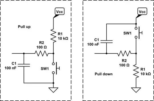
I built the HEX file correctly and downloaded it to the MCU (without any problem or errors). Now, when I run it, there is a problem. The LED blinks quickly even when I don't press the button. Look:

Why? Also when I press the button, it toggles the LED but it blinks between each press. It looks like something changes the state of PB1 pin. What's the problem? How can I correct it?