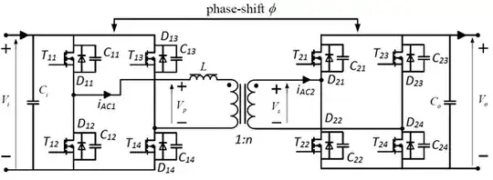
I'm having issues calculating the power losses associated with the operation of a bidirectional isolated dual active bridge DC/DC converter. The converter is controlled using phase shift modulation (PSM.) The converter is shown below. There are 4 "switches" on each bridge (switch here meaning a parallel combination of MOSFET, anti-parallel diode and capacitor.)
The switching cycle can be broken into 4 main intervals, not accounting for transitions between these intervals. During each of these 4 intervals, two MOSFETs on each of the bridges conduct. During the transitions between intervals, certain capacitors and diodes also conduct. In order to illustrate the logic behind this, the following diagrams and tables are provided. N.B. The circuit diagrams are incomplete, however, the remaining circuits which have been omitted follow the same trend indicated by the diagrams given.
Switching Cycle Circuit Diagrams:
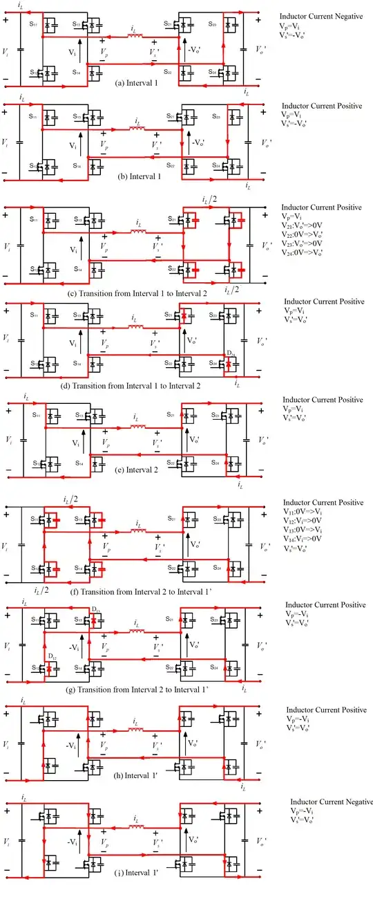
Current and Voltage During Intervals:

My goal is to calculate the power losses in the converter during a switching cycle.
I am aiming for my total losses figure to include core losses, conduction losses of diodes and MOSFET and switching losses. In relation to switching, zero voltage switching can occur under certain conditions, in which case the switching losses for the switching question will be given as zero.
Now for my question:
The plot of current and voltages above only shows periods where the MOSFET are conducting. In this ideal case, I understand that conduction loss would simply be the square of the RMS current by the resistance of the MOSFET in question. My issue relates to the period of time for which the diodes and capacitors conduct during the transition period between intervals. In order to calculate the conduction losses in the diodes, I will need to identify this time period.
Can somebody explain how to calculate the losses in the devices during these transient periods?


