10

How can I compute the differential impedance of an Edge-Coupled Coplanar Waveguide With Ground?

I couldn't find any free calculator online, so I wrote a small program which computes the the impedances of an Edge-Coupled CPWG and compared the result of an example calculation with values I could find at http://www.edaboard.com/thread216775.html#post919550 (a screenshot of Si6000 PCB Controlled Impedance Field Solver). For some reason my result appears to be wrong.

So I tried the following manual computation with the same solution. Where did I go wrong?

I used the equations from Coplanar Waveguide Circuits, Components, and Systems from Rainee N. Simons (2001). The Edge-Coupled CPWG can be found at pages 190-193.

My Calculation

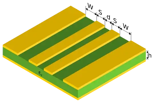
Let \$h = 1.6, S=0.35, W = 0.15, d = 0.15, \epsilon_r = 4.6\$.

Edge-Coupled Coplanar Waveguide With Ground

$$r=\frac{d}{d+2S} = \frac{3}{17}$$ $$k_1 =\frac{d+2S}{d+2S+2W}=\frac{17}{23}$$ $$\delta =\left\{\frac{(1-r^2)}{(1-k_1^2 r^2)} \right\}^{1/2} \approx 0.992787$$

$$\phi_4 = \frac{1}{2}\sinh^2\left[ \frac{\pi}{2h}\left(\frac{d}{2} + S +W\right)\right] \approx 0.176993$$ $$\phi_5 = \sinh^2\left[\frac{\pi}{2h}\left(\frac{d}{2} +S \right)\right] - \phi_4 \approx 0.007438$$ $$\phi_6 = \sinh^2\left[ \frac{\pi d}{4h}\right] - \phi_4 \approx -0.171561$$

$$ k_0 = \phi_4 \frac{-(\phi_4^2-\phi_5^2)^{1/2} + (\phi_4^2 -\phi_6^2)^{1/2}}{\phi_6(\phi_4^2-\phi_5^2)^{1/2} + \phi5(\phi_4^2 -\phi_6^2)^{1/2}}\approx 0.786198$$ $$\epsilon_{\mathrm{eff, o}} =\frac{\left[2\epsilon_r \frac{K(k_o)}{K'(k_o)} + \frac{K(\delta)}{K'(\delta)} \right]}{\left[2\frac{K(k_o)}{K'(k_o)} + \frac{K(\delta)}{K'(\delta)} \right]}\approx 2.800421$$

$$z_{0,o}=\frac{120\pi}{\sqrt{\epsilon_{\mathrm{eff, o}}} \left[2\frac{K(k_o)}{K'(k_o)} + \frac{K(\delta)}{K'(\delta)} \right]}\approx 50.4850\qquad(\Omega)$$ $$z_\mathrm{diff}=2\cdot z_\mathrm{odd}\approx 100,97\neq 89,67\qquad(\Omega)$$

with \$K(k)\$ the complete elliptic integral of the first kind and \$K'(k)=K\left(\sqrt{1-k^2}\right)\$

I wasn't sure about the curly braces in the \$\delta\$ equation and just assumed the author went out of braces ;).


Quick Update:

I just found atlc. A very useful numeric Impedance calculator. I let it run

create_bmp_for_microstrip_coupler -b 8 0.35 0.15 0.15 1.6 0.035 1 4.6 out.bmp
atlc -d 0xac82ac=4.6 out.bmp

and the result is reasonable close to SI6000.

out.bmp 3 Er_odd=   2.511 Er_even=   2.618 Zodd=  46.630 Zeven=  99.399 Zo=  68.081 Zdiff=  93.260 Zcomm=  49.699 Ohms VERSION=4.6.1
someonr
  • 305
  • 1
  • 4
  • 15
  • Just starting to think, that this question might be better for physics.SX? – someonr Jun 30 '14 at 16:30
  • 1
    Maybe on Computational Science SE, but it also fits here. This is a question that's going to be useful for a lot more engineers than physicists. – The Photon Jun 30 '14 at 18:19
  • FYI, you have your W and S parameters swapped from the way I normally see them defined. This could mess you up as you transfer values between different tools. – The Photon Jun 30 '14 at 18:26
  • @ThePhoton I already noticed that they are swapped. I just used the notation from Coplanar Waveguide Circuits, Components, and Systems. – someonr Jun 30 '14 at 18:45
  • Any newcomers, check out "iCD Design Integrity". They have a calculator for "Dual Strip Coplanar Waveguide Grounded (CPWG)" free trial. – Keegan Jay Sep 22 '17 at 17:41

2 Answers2

4

It doesn't look like you have gone wrong.

Agilent's LineCalc tool calculates Zodd = 50.6 ohms and Zeven = 110 ohms for your geometry, very close to your result. This assumes ~0 trace thickness.

Incidentally, the trace thickness parameter does have a significant effect. With t = 35 um (typical for copper with plating on a pcb), Zodd drops to 44 ohms, according to LineCalc.

The Photon
  • 126,425
  • 3
  • 159
  • 304
  • Thx, looks like this is the problem. Now need to see how to include the thickness. – someonr Jun 30 '14 at 18:46
  • Incidentally, I'm not sure the LineCalc geometry includes the ground plane. However, given the 10-to-1 ratio between h and d, it's probably a small effect. – The Photon Jun 30 '14 at 18:49
  • How sure are you that the effect is small? The numerical solution of `atlc` is \$Z_\mathrm{odd}=50.092, Z_\mathrm{diff}=100.185\$ (with t = 0.035). That would be closer to my solution. – someonr Jun 30 '14 at 19:11
  • If I was going to design with these numbers, I would check with a field solver (like atlc). Or just go ahead with "close-enough" numbers and have my fab shop fix things up (but my fab shops use Polar for these kind of calculations, so I trust them to do that). – The Photon Jun 30 '14 at 19:21
  • Just noticed that I had the wrong \$\epsilon_r\$ for `atlc`. Looks like you are correct. – someonr Jun 30 '14 at 22:59
2

There's a free calculator for edge-coupled transmission lines. It comes with the simulator package QucsStudio, but is a standalone application. Just look at: http://dd6um.darc.de/QucsStudio/tline.png or http://dd6um.darc.de/QucsStudio/about.html