3

I've been working with an Arduino lately, and building various breadboard circuits.

A simple example was to build a transistor based inverter for a project involving 9600 baud serial combination at 5v. (I could do it with a quad NOR gate, but that is a 14 pin DIP package that needs 12 wires connected (when you include tying unused inputs to ground. That takes a lot of room on my breadboard and a lot of time to set up. I understand that a "real" CMOS inverter is a better choice for this application, but bear with me.)

I built an inverter based on this thread:

How to invert a digital signal

The circuit looks like this:

enter image description here

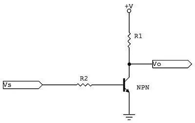
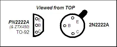
If I use r2 = 100k ohms and r1 at 3.3k ohms, it works, when using a general purpose NPN transistor like a 2222A or a CP9014. If I use a "switching" NPN transistor like a C1740, however, it doesn't work.

What is it about switching transistors that makes them unsuitable for a circuit like this? I thought switching transistors were tuned for very "snappy" response that tends to be either fully on or fully off. I would think a switching transistor would be a BETTER choice for this circuit, since I want it to be either fully on or fully off.

Duncan C
  • 1,398
  • 2
  • 15
  • 27
  • Might be a silly question but did you check the pinout of the switching device? – user34920 Jun 29 '14 at 19:52
  • I could not find datasheet for the C1740. Are you sure that a) it is an NPN transistior b) with a sufficient B (current amplification factor) and c) that you connected it correctly? Also, I would use a much lower resistor instead of 100k, maybe 10k. – Wouter van Ooijen Jun 29 '14 at 19:52
  • 1
    Describe "not work". V0 always high? Poor logic levels? n.b. saturation is usually defined as Hfe=10, at which point R2 should be 10*R1 not 33*R1. –  Jun 29 '14 at 19:54
  • @BrianDrummond, Saturated means fully on/off? So is that a rule of thumb, make r2 10x the r1 value? Exactly 10x, or 10 or less? And how large an R1 can I get away with and still see 5V on the output (Very high impedance CMOS output). – Duncan C Jun 29 '14 at 20:32
  • Saturated means fully on; and 10 more or less (20 is *usually* OK and saves base current. 30 is *often* OK and may be fine now you have found the REAL problem.) –  Jun 29 '14 at 21:07

1 Answers1

4

Maybe it's a 2SC1740: -

enter image description here

If so, note the pins (red line) - they are not the standard pin-out with base in the centre like the 2N222A: -

enter image description here

Andy aka
  • 434,556
  • 28
  • 351
  • 777
  • I don't know for sure what these are. These are loose parts that I've collected in various electronics kits and projects through the years. I have one that says C1740 RB and the other says C1740 RC (where there is a bar over the B in "RB" and over the C in "RC" on each component. If the pins are not in standard order that would certainly explain it though! – Duncan C Jun 29 '14 at 20:29
  • I'm having a little trouble understanding the pinout diagram from that data sheet. Is the flat side facing up in the red box above? So the leftmost pin is the emitter, the middle is the collector, and the rightmost pin is the base? (The base and collector are reversed from the 2n222A?) – Duncan C Jun 29 '14 at 20:35
  • @DuncanC I would say that in the diagram where I drew the red box the flat side is facing the reader. Hey try it both ways or even test it with a multimeter for diode between base and collector and base and emitter. – Andy aka Jun 29 '14 at 20:38
  • Woo-hoo, that's it! I just swapped the base and collector in my breadboard, and now the C1740 works in place of the 2222A. Thank you very much. It's maddening that the pinouts aren't the same. Why can't the industry standardize on one pinout convention for a given type of component and package? (e.g. NPN transistors in TO-92 packages are always E/B/C when viewed from the top with the flat side facing forward) – Duncan C Jun 29 '14 at 20:55
  • aaah yes, the infamous TO-92 rewiring. BC214 and BC214L were nominally identical ... except for the pinout! –  Jun 29 '14 at 21:08
  • The same component, just different pinouts? oh lordy, that's awful. – Duncan C Jun 29 '14 at 21:17
  • 3
    Golden rule - always read the data sheet and if you can't find one then don't assume. – Andy aka Jun 29 '14 at 21:18