0

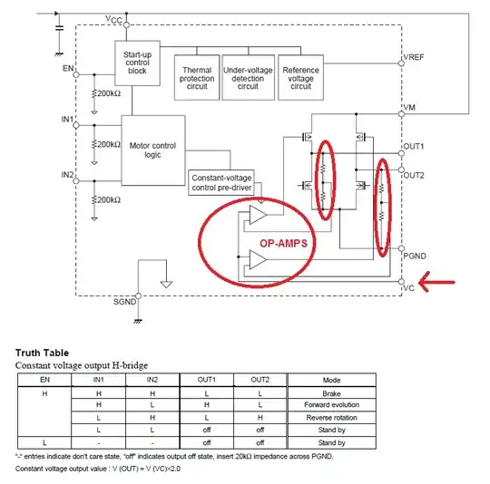
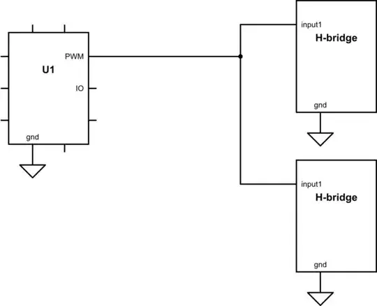
I am using ATMega16L and I'm using two DC motors to build an autonomous robot. I want to use an h-bridge to control the two motors. Can I use a single PWM output from say Timer1 on the microcontroller to control two h-briges so that the motors can go forward at the same speed, go reverse at the same speed and change direction by making one motor go forward and the other in reverse?

Can I connect OC1A PWM output from the microcontroller to be an input to 'IN1' pin on both h-bridges while 'IN2' is low so that robot goes forward and vice-versa to make the robot go backwards. I am not sure how to connect the circuit to share OC1A output to control these h-bridges.

David Norman
  • 1,475
  • 2
  • 20
  • 31

3 Answers3

3

If you are happy with the specified H bridge only being able to supply 0.5 amps absolute maximum whilst "dropping" about 1 volt with the high-ish on-resistance of the MOSFETs in the package, it can be made to work. The data sheet showed an application where it runs from a 3V supply - it's a feeble little device and there are significantly better devices available.

See also my post on this subject.

Really this device is intended for an analogue control of the motors. Note the diagram below: -

enter image description here

If you read the spec you'll see that the rise time and fall times are about 1 to 2 us so your PWM control needs to be limited to maybe about 50 kHz - you'll also need to setup the control voltage Vc - see the feedback resistors and op-amps - they ultimately control the voltage that the motor sees so PWM will work but you may be better just using a filter from the PWM signal to create an analogue voltage and feed this into Vc.

At 90mA and 3 volts, the power is 270mW and this is acceptably inside the absolute max rating of 700mW but the device will get warm and "lose" battery energy.

Andy aka
  • 434,556
  • 28
  • 351
  • 777
  • 0.5amps is enough as I need to drive 2 tiny coin vibration motors rated at 3V, 90mA – David Norman Jun 24 '14 at 09:22
  • @DavidNorman OK 90 mA sounds cool but you need to control the Vc pin too and, it might be advantageous to filter your PWM to a DC level and use this inputted to the Vc pin. See adds in my answer. – Andy aka Jun 24 '14 at 09:47
  • These OPAMPs act sort of like a comparator right? What role does Vc play as compared to IN1 and IN2. Why is it even there when there are inputs? – David Norman Jun 24 '14 at 21:21
  • I believe these op-amps control the voltage via linear methods i.e. they try and set OUT1 (or OUT2) to a fixed voltage rather like a linear series voltage regulator. The giveaway (to me) is the potential divider. In1 and 2 can somewhat override the output i.e. it can switch it off (it seems) but it can only force the output to be as high as twice Vcontrol. So when it says "H" in the truth table in my answer, H = 2*Vc – Andy aka Jun 24 '14 at 21:25
  • I see. What if I connect Vc directly to VCC i.e. 3.3V? I was looking at its application notes (http://www.onsemi.com/pub_link/Collateral/ANDLV8075LP-D.PDF) and they say 'Must be short-circuited to VCC pin when using saturation control'. Now what is this suppose to mean? the word 'saturation' doesn't make sense to me – David Norman Jun 24 '14 at 21:54
  • its talking about saturated transistors I.e. fully on and not acting as a voltage regulator as I mentioned above. It should be ok but keep pwm frequency to below 50kHz. – Andy aka Jun 24 '14 at 22:06
  • I'm relieved hearing that it should be OK. I am using vibration motors to move a robot in a certain direction, the max PWM frequency that I will be using is probably 20 Khz. I really appreciate the time you have put into answering this question. Thanks Andy – David Norman Jun 24 '14 at 22:17
  • What is meant by Constant-Voltage control? This h bridge provides constant voltage does that mean it can only be used for either switching on or off of the motors? – David Norman Jun 25 '14 at 05:18
  • Constant voltage control is what I was describing with the op-amps. Switching on and off is what you want to do - the data sheet suggests rise and fall times. I've mentioned these once in my answer. – Andy aka Jun 25 '14 at 07:10
  • I read your answer, but what I'm still confused about is will I be able to use PWM to vary the speed of the motor while VC is connected to VCC. Because connecting VC to VCC will send the outputs on full drive right? – David Norman Jun 25 '14 at 07:18
  • That's how PWM works dude - full +drive then full -drive. If in doubt filter your PWM signal to an analogue value and do linear control. The motor power hardly justifies doing full PWM. – Andy aka Jun 25 '14 at 07:35
  • oh crap. I have been looking at it all wrong. So when using PWM and when the signal goes 'high' the transistor is set to be in full drive for x micro seconds right? – David Norman Jun 25 '14 at 07:40
  • That's how I assume it works - that's "normal". – Andy aka Jun 25 '14 at 08:09
1

Sure you can do that without any problems Just make sure all the grounds (gnd's) are connected together. but do you mean IN1 = IN2 or IN1 = inverse IN2 for the last case you need to put an invertor behind it

If you have any more questions feel free to ask

schematic

simulate this circuit – Schematic created using CircuitLab

Bruce
  • 1,051
  • 7
  • 17
1

Parallax make a h bridge. Hb50. You can link 2 together off the 1 input and control them separately. That way you can have 2 motors working independently of each other but sharing 1 pin on the microcontroller