2

I have a GPS PCB which has regular USB pinouts (GND, +5V, DATA- and DATA+), but in addition has one stranded wire which is connected to USB type A plug. Marked as "USB connector" on the image:

GPS PCB

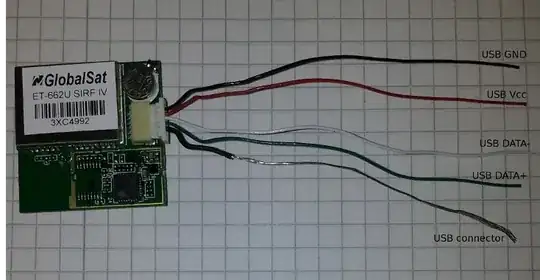
What is the purpose of this stranded wire? If this is for shielding purposes, then why is it connected in both ends? Doesn't this create a "shielding loop"? In addition, if this matters, there is an aluminium-foil shielding around all five wires:

enter image description here

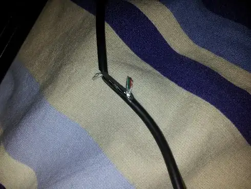
..and this aluminium-foil is also connected to USB plug, i.e. aluminium-foil and stranded wire are electrically connected.

Martin
  • 269
  • 3
  • 11
  • 1
    It probably serves the same purpose as the drain wire in an audio cable. See [this question](http://electronics.stackexchange.com/q/108306/2028) I asked about it. – JYelton Jun 23 '14 at 21:56
  • 1
    JYelton, thanks! So the drain wire has exactly the same purpose as aluminium-foil but it's just easier to connect to connectors? Still, I'm bit puzzled how the overall shileding should work. There are three ground "wires"- aluminium-foil, drain wire and black USB GND wire. They are all connected to each other. Now what exactly happens in case of EMI? – Martin Jun 23 '14 at 23:12

0 Answers0