Here is the schematic of the circuit I'm trying to build (source) but I only have an IRF9530N Mosfet; I don't have any NPN transistors at hand.
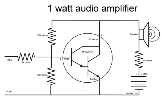
What would the schematic look like with a MOSFET instead of the NPN?
Here is the schematic of the circuit I'm trying to build (source) but I only have an IRF9530N Mosfet; I don't have any NPN transistors at hand.
What would the schematic look like with a MOSFET instead of the NPN?
Bipolar transistors are cheap and available. Get some.
This is a pretty crappy circuit in the first place. It is in no way capable of providing 1 W of AC power into the speaker. Even ignoring the inevitable off-center biasing of the transistor and any voltage drop accross it, at best this circuit is a 4.5 Vpp AC source with 50 Ω output impedance. 4.5 Vpp is 3.2 V RMS. The highest power transfer happens when the load impedance matches the source impedance, in other words when the speaker is also 50 Ω. That means the load (the speaker) will see half the open circuit RMS voltage, which is 1.6 V. (1.6 V)2 / 50 Ω = 51 mW. Or about 1/20 of the advertised output power. With a typical 8 Ω speaker, the output power will be considerably lower than that.
Another problem with this circuit is that it puts DC current thru the speaker. That's generally not a good idea, but at these low power levels won't cause any harm to a normal size speaker. This circuit is so poor that the additional distortion caused by DC thru the speaker is the least of the problems.
This circuit could work with a N channel MOSFET replacing the darlington, but the same output power calculations still apply. MOSFETs don't have as well a defined gate voltage threshold where they quickly change between off and on. Because of that, the bias point produced by the two 100 kΩ resistors can't be computed up front. If this is just for experimenting, use a 100-500 kΩ pot for the two bias resistors and adjust it so that the drain sits at about half the supply voltage (4.5 V) when there is no input signal.
In answer to your question, this is how your circuit would look if you replaced the bipolar Darlington with a MOSFET:
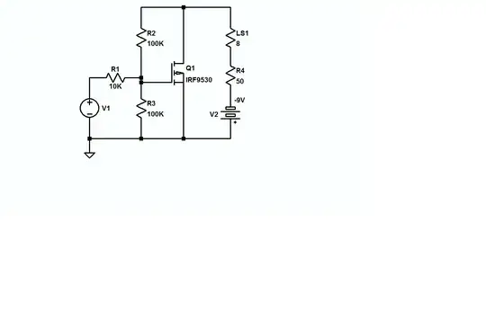
Notice that an IRF 9530 is not N-channel, it's a P-channel MOSFET, so the supply polarity has been reversed.
This circuit is fraught with problems and is barely suitable for experimentation, but for starters I'd cap-couple the source and the load to the circuit and then work with the biasing and feedback.