3

Is it possible for me to locate my ammeter and shunt a few meters away from each other (more than intended by original wiring)?

The extra wiring obviously has a resistance and provokes a false reading, which I have tested and found to be true.

Is there a way I can locate my ammeter away from my shunt?


It's a 12V DC circuit running from around 0 Amps to 10 Amps, Ammeter is rated to 50 Amps and the shunt is 75mv. "False readings" are the ammeter showing anything from 0 Amps to 12 Amps when I know it is 1.7 Amps depending on the extension of wires I try'd. I'm hopeful about trying to eliminate the noise and will report back when I've tested.

Dave Tweed
  • 168,369
  • 17
  • 228
  • 393
user45878
  • 31
  • 2

2 Answers2

2

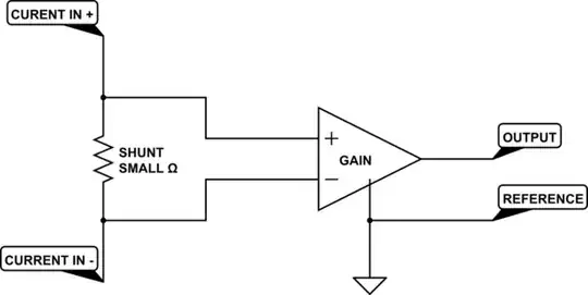
Alex Freeman to the contrary, you should have no problem with the resistance of the extension. An ammeter which uses an external shunt looks something like

schematic

simulate this circuit – Schematic created using CircuitLab

The gain amplifier will normally have a fairly high impedance, so the added resistance of the leads should not be a problem. What you do need to watch out for, though, is noise pickup on your extension. The shunt, extension wire and amplifier make a loop, and any net magnetic fields within the loop will induce currents. Since the impedance of the amplifier is high, even very small currents will produce relatively large voltages. Stray 60 Hz is a common source of unwanted nasties. The solution is to use twisted pair for the extension, and perhaps (if the situation calls for it), shielded twisted pair.

WhatRoughBeast
  • 59,978
  • 2
  • 37
  • 97
  • If the entire shunt circuit is passive and uses a d'Arsonval or other type of mechanical moving coil meter for the indicator, then the calibrated-in burden on the load circuit will include the leads to the meter and will change the calibration and introduce error if the length of the meter leads is changed. – EM Fields Jun 20 '14 at 13:28
0

In brief, yes, theoretically, but you'll probably end up introducing a large discrepancy in current especially at low loads, and if you don't accurately measure the offset caused by the additional resistances, your measurements are going to be well off anyway. So yes, but avoid unless absolutely necessary.

In more detail: Assuming temperature isn't an issue (shunt resistors are normally made of manganin, since its resistivity changes very little with temperature, unlike other conductors), as long as you know the resistance and thus voltage drop of your wires, you will still be able to use it as an ammeter after adjusting for the larger drop. It won't be as effective since the higher resistance will reduce current more, and the reading will be less accurate since extra uncertain factors (e.g. length of wire) will be introduced, but it is theoretically possible.

You'd need to be able to measure the resistance or voltage drop fairly accurately though. This can be done with a wheatstone bridge, but the resistance needed for that generally needs to be higher than about 1 ohm; comparing this with a typical shunt resistor rated at 10A, 75mV drop - i.e. 0.075/10 = 0.0075 ohms, it's a lot higher, so I doubt it would be suitable for low power or very high power applications. You could try making a Kelvin bridge, although that involves getting very high precision resistors; I've never tried so I can't tell you too much about this, but they are apparently better at measuring resistances below 1 ohm.

If you have a current source or power supply with precise current limitation, you could use that along with a multimeter to inject a known current into the connecting wires and by measuring the voltage across it, deduce the resistance.
Alex Freeman
  • 557
  • 1
  • 8
  • 20