3

I am struggling with a completely self built/written quad copter I am working on.

I am working on the PID controller for balance, right now just with a P value and it only reacts on ROLL and PITCH to minimize potential errors. I put the prototype on a box and use ropes to restrain it so it can not damage something/me.

My main question is currently related to the motor controll function.

Currently my PID controller gives me a number from -1024 to +1024 for each axis depending on tilt etc.

Currently I use this value, multiply it by 0.4 and ADD/DEDUCT it from the global THROTTLE variable.
So each motor receives THROTTLE (0-1000) and then depending on its position the PID value*0.4 is added/deducted to/from the THROTTLE. 1000 would be max power, 0 would be minimal power.

I am new to motor control with air vehicles and I think the way I control the motor is not right for a stable balancing.

What is a good way to control the motor power based on a PID value ? So right now I use an absolute value based on what my PID returns, regardless of throttle.

Aside from the fact that I will still have to tweak that value as it would cause a crash on startup (the absolute value from the PID would be higher than the total throttle) I have a bad feeling in general about it.

My main concern is that this approach is fast in calculation (no divisions etc) but the PID values are always in the same range while the THROTTLE can be low (start). So on lower THROTTLE values the same tilt currently results in a stronger response than on high THROTTLE values.

I am sure someone with more experience than me could light me up how to properly tune the motor power based on the PID output.
Roh
  • 4,598
  • 6
  • 41
  • 86
John
  • 213
  • 3
  • 12

2 Answers2

2

This seems like more of an aerodynamics question, but I'll take a shot at it.

Maybe what you're talking about is to adjust in terms of percent of THROTTLE? building on your technique this might be

$$OUTPUT = Error * 0.4 * {THROTTLE\over THROTTLE_{max}} + THROTTLE$$

Factoring out THROTTLE,

$$OUTPUT = (Error * {0.4\over THROTTLE_{max}} + 1) * THROTTLE$$

Now considering that $${0.4\over THROTTLE_{max}}$$ is a constant, this is only two multiplies and one addition.


I think though if your throttle output is linear (ie if throttle is proportional to force) the restorative forces to tip the thing back to level should be the same regardless of how high the throttle is set... Said another way, it doesn't take any more or less force to rotate the 'copter no matter how fast it's going.

Hopefully this helps. It's WAAY outside my area of expertise haha

Daniel
  • 6,168
  • 21
  • 33
  • A simple conclusion and probably correct, never looked at it from that angle :) I will stick to absolute values and try to find out the right ones. On PID, in case you have experience here: As I made my mind: The PId KP term will have to do the main work (so that value counts most), KI is just to align on longterm errors (battery, motor differences, etc) and KD to react more exactly (reducing overswing etc). So my approach to ignore KI and KD for now an djust try to get the thing somewhat stable with KP and gain (0.4 atm) is correct? – John Jun 19 '14 at 14:54
  • I'm not experienced with tuning PIDs, but what you're talking about doing is using it as a PD or a PI controller, which you should be able to find tuning guidelines for. – Daniel Jun 19 '14 at 17:09
0

I'm not an expert on quadcopters but I do know about control.

If I understood you correctly, Throttle is your user input or "setpoint" and you're feeding that directly to the motors with the PIDs giving an additional effect depending on the control errors.

This is a very unusual approach. The role of the I term in PID is to set the average or steady-state value for the motor. Basically any non-zero error will cause the integrator to ramp (up or down) so it settles out to a steady value when the error becomes zero. So the I output must be the steady state value required for zero error. It looks like you are trying to override this by feeding forward the Throttle value, which you could do, but is probably not what you want.

All PIDs require a setpoint and a measured value (from the 'copter). The setpoints will need to be in the same form as the value being measured so the they can be subtracted to form an error signal which is the input to the PID. You can't add apples and oranges to get more apples is what I learned in school. So sensors being Angle and Rotation, then they also need to be setpoints.

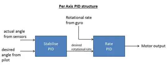
I was curious so I did a quick search and sure enough this is what's done

Notice there are 2 PIDs. One taking Angle and outputing rotational rate, the other taking rotational rate as its setpoint and comparing to the measured rate from the Gyro.

enter image description here

akellyirl
  • 4,117
  • 1
  • 16
  • 30
  • It seems like the global throttle setting has been left out here, so the "Motor output" is the 'motor output adjustment term', ie motor = Motor output + global_throttle. The global_throttle that I'm talking about is the signal you're sending to ALL motors, to raise or lower altitude. Notice in the graph there's no input for 'desired throttle setting' – Daniel Jun 19 '14 at 17:16