4

I recently saw an article with a LED cube 8x8x8. I saw that it relies on an optical phenomenon called persistence of vision (POV).

So I wanted to create a simple circuit with 4 lines each one with one LED, that will light up with a frequency that will give the illusion that they light up all the time. (I know how to light up 4 LEDs but I want it simple now to catch the point)

Can someone help me and tell me what parts should I need to create this? I have an Atmega 16L microcontroller. Can I complete this without any other chip? Can I achieve this also with 555 and flip flops?

EDIT:

Sorry if I cant be understandable.

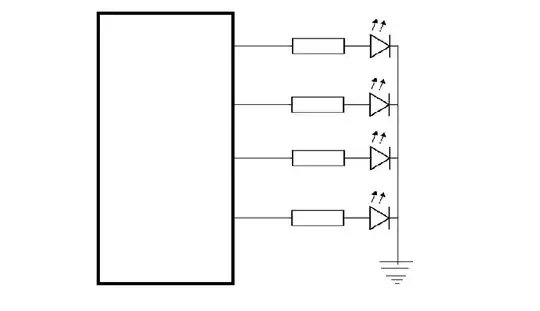
I want a simple circuit like the one in the below picture that will light up each strip for a certain time.This time must be sort enough to see a constant lighting.

The black box is whatever parts it will need because I dont know them.

enter image description here

Dave Tweed
  • 168,369
  • 17
  • 228
  • 393
konsalex
  • 229
  • 4
  • 13
  • 2
    There are two techniques that use POV: time-multiplexing (as probably used in the 8x8x8 cube), and mechanical (moving) 'location multiplexing', as used in magic message wands. To which are you referring? – Wouter van Ooijen Jun 17 '14 at 12:07
  • "light up with a frequency that will give the illusion [...]" - Hint: Some 50-100hz can be enough when there's no/slow relative motion of LED and observer, 1000hz will be enough for almost all use cases (except maybe aviation or space craft use); this can easily be achieved with an AVR. – JimmyB Jun 17 '14 at 14:43
  • I want it to seem like it light up so smooth like it is connected to Vcc straight up.In the cube frequency is 1.4 Mhz.Its a big difference. – konsalex Jun 17 '14 at 14:52
  • So you're just interested in learning how to multiplex LEDs, instead of more complex POV effects? If that's the case, see this [Google search](https://www.google.com/search?hl=en&q=multiplexing+leds&safe=active&gws_rd=ssl) – Ricardo Jun 17 '14 at 15:02
  • The black box can just be the ATMega. No need for extra hardware. Just do `digitalWrite(1,HIGH);delay(10);digitalWrite(1,LOW); digitalWrite(2,HIGH);delay(10);digitalWrite(2,LOW); ...` – Gerben Jun 17 '14 at 16:13
  • this write in the hex code that i ll burn in atmega? – konsalex Jun 17 '14 at 16:15
  • and where should i connect the wires?I mean in what pins – konsalex Jun 17 '14 at 16:15
  • That's not even a sentence! Please rephrase so I can understand what you are asking. – Gerben Jun 17 '14 at 16:16
  • You can pretty much use any pin on the ATMega16. – Gerben Jun 17 '14 at 16:18
  • Sorry for my english.I should write this code in the hex that i ll burn in atmega?And which pins should i use and connect them to LEDs? – konsalex Jun 17 '14 at 16:22
  • Why would you want to write your code in hex? Just write it in C and let the compiler (avr-gcc) make the hex for you. – Gerben Jun 17 '14 at 16:29
  • What do you suggest a micocontroller or the circuit with flip-flops down in this page ? And with what I can achieve higher frequence. – konsalex Jun 17 '14 at 18:28

3 Answers3

5

Yes, you can do a POV application with your ATmega16L and a bunch of LEDs and resistors and some clever programming.

The simplest POV application I've seen and that I have incidentally built is an Arduino shield called Blinkenlight.

This particular board has a set of 20 inline LEDs that you can program to display the POV effect. You can then achieve the POV effect by waving it around in the dark. So, it's mechanical and human powered (yes, your arm will get tired after playing with it for a while).

Image of Blinkenlight Arduino shield

It's based on Arduino Uno and related boards, but you can easily build your own standalone version and even modify it to use your ATmega16L.

Here's a few pictures of the POV effect in action:

POV effect example 1 POV effect example 2 POV effect example 3

The idea behind the circuit is quite simple, you just have to wire a LED and its corresponding series current limiting resistor to every digital output pins you have available (as in the schematic below). The rest is programming.

Blinken light schematics

The board can do a few other tricks as well, such as The Night Rider effect and more.

Ricardo
  • 6,134
  • 19
  • 52
  • 85
3

As asked for, here's one way to do it in hardware:

enter image description here

R1C1 is an integrator used to reset U1 and U2 on power-up, U3B and U3C are leftover gates wired to make an astable multivibrator with C2 and R6 determining the frequency of oscillation, and they generate the clock for U1 and U2, a couple of dual "D" type flip-flops which generate a positive going pulse used to drive the LEDs.

The pulse is mutually exclusive, so it only lights one LED at a time, and it circulates through the dflops, one at a time, from U1A to U1B, to U2A, to U2B, and then back to U1A to repeat the cycle anew.

EM Fields
  • 17,377
  • 2
  • 19
  • 23
  • The frequency of this clock? – konsalex Jun 17 '14 at 15:50
  • With the values shown on the drawing, it's about 2.4kHz. – EM Fields Jun 17 '14 at 16:25
  • How do you calculate it and what is the max frequence that I can achieve? – konsalex Jun 17 '14 at 18:29
  • With Vcc = 5v and D7 and D8 in there, f ~ 1.5RC. With Vcc = 5V and the diodes out of there, f ~ 2.2 RC. The maximum frequency, I think, is a couple of gate delays, which for the the HC10 would be about 100ns, or 10MHz. If you want the LTspice model to play with, it's at https://www.dropbox.com/sh/jgujxgeg2m73rpw/AABgQ93g4xF-FwY9B4b6GInsa and if you need the simulator it's free and it's at: http://www.linear.com/designtools/software/ – EM Fields Jun 17 '14 at 19:34
2

The black box can be a four bit shift register. You just need:

  • a configuration such that the bit shifted out of the most significant bit feeds into the least significant bit.
  • ensure that the shift register is loaded with 0001 on power up.
  • feed a clock signal to drive it.

For instance, take a look at the datasheet for the SN54.

This IC has parallel inputs which are read when the S pin is held low, and the CP1 pin transitions from high to low. So you can just tie these pins to high or low voltage to create the pattern 0001, and ensure that your circuit generates a power-on-reset pulse which holds S slow for a while, and have a clock pulse going on CP2.

The clock can be generated with some multivibrator circuit, for instance.

Power-on-reset pulses can be created with a RC circuit and comparator (charging of a capacitor until a threshold is reached).

Kaz
  • 19,838
  • 1
  • 39
  • 82
  • There was a worthwhile comment here by someone else that the SN54 is an old hard-to-source part which cannot drive LEDs directly. The main idea is the shift register; find a more suitable part. – Kaz Jul 09 '14 at 17:56