4

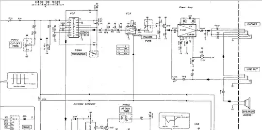
I was looking at the attached schematic and realized that all opamps and transistors are "flipped" in respect to their power pins. I realize that this is only another way of writing the same thing with +9V on the positive rail and GND on the negative one, so what's the point of this?

Bonus question: Why are the headphones and the Line Out in rerence to GND (positive rail) and the built-in speaker in reference to -9V (negative rail)?

enter image description here

JYelton
  • 32,302
  • 33
  • 134
  • 249
user35474
  • 87
  • 2
  • Appears to be from the [service manual for the Yamaha CS1](http://www.bleeps-and-peeps.com/images/stories/hardware/yamaha/cs1/service_manual/yamaha%20cs1%20servicemanual.pdf) – Kaz Jun 17 '14 at 01:20
  • Yes, yes, you're right. I want to mod mine, that's why I looked at this schematic in the first place. Then I realized the "flipped" power supply. I only know this from fuzz pedals which are often "positive ground" circuits. – user35474 Jun 17 '14 at 08:36

3 Answers3

1

A possible reason is that some of the IC's, like that IG021610 part, seem to be designed for a negative supply (the power pins are actually labeled GND and VEE). So the other ones that can be used either way are just adapted to that supply. Their signal inputs and outputs are capactively coupled, and so the absolute voltage at which those chips operate doesn't matter.

Kaz
  • 19,838
  • 1
  • 39
  • 82
1

Telephony systems originally operated at negative voltages for cathodic protection reasons. There is an interesting Q & A here about that.

I suspect that these devices (or some subset of the design) was designed using parts that were originally intended for telephony designs.

Either that or this was designed to be operated in the shower ... ;)

placeholder
  • 29,982
  • 10
  • 63
  • 110
  • Or it is from a time when PNP transistors were primarily used. PNPs are easier to work with when the ground is positive. – Pentium100 Aug 16 '14 at 20:47
0

Assuming this op-amp is a differential amplifier, it likely contains an emitter-coupled pair (also known as a "long-tailed pair"). If you only have a single supply to work from, these pairs work best with ground as the positive-most point in the circuit because it provides better noise immunity.

enter image description here

I could go into further detail about how this configuration improves noise figure, but you are likely to find a better explanation in an analog electronics book. One book that goes into more detail is Microelectronic Circuit Design by Richard Jaeger, although I am sure there are cheaper books which cover the same topics.

Ryan
  • 230
  • 1
  • 12