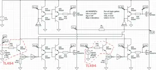
First, what you show isn't really totem pole but bi-directional emitter follower.
Your basic concept makes sense in that the emitter followers will have current gain equal to the gain of the transistors. However, a problem is that each bi-directional emitter follower stage will lose two junction drops of voltage swing.
Using a single emitter follower stage to drive a FET gate can be appropriate, and I have done exactly that in production designs. However, you have to make sure the FET is still driven to the necessary min/max voltage for good switching. When you're only starting with logic level voltages, losing one junction drop on each side could be a challenge. Losing 4 junction drops due to two cascaded stages most likely won't work. Even with a 5 V logic signal, you'd be left with only around 2.2 V swing on the FET gate.
However, I don't see the point to two current gain stages. You can easily find transistors with a minimum guaranteed gain of 50 for your current and voltages. Actually 100 shouldn't be hard to find with minimal searching. Given that kind of gain available in a single stage, you shouldn't need two stages. 8 mA from your logic gate turns into 800 mA at the FET gate. If you need more than that, you should be using FET driver chips that are intended just for that purpose.
You should also ask yourself whether the logic gate by itself is enough. The gate will be driven a bit slower due to the limited current to charge or discharge the gate capacitance, but does that really matter in your design? I've done lots of designs with microcontroller pins directly driving "logic level" low side N channel switches. If you're only switching a solenoid with 24 kHz PWM, for example, you probably don't need any current gain at all.


