9

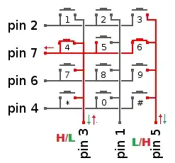
I am designing a keypad in VHDL. Everything works fine when only a single key is pressed. I'm scanning each column for a key press in a state machine and when no key is pressed, which is the condition pin4pin6pin7pin2 = "0000" I switch to next state for scanning the next column. Thus I set the columns pin3pin1pin5 sequentially to "001", "010" and "100".

While scanning pin3pin1pin5 as "001" and if pin4pin6pin7pin2 is "0100" then simply "9" is pressed. I declare in VHDL pin4pin6pin7pin2 as input and pin3pin1pin5 as output ports. When I press 6 and 9 at the same time pin6 and pin7 are high. The first pressed key is read, the second one is ignored. When I press 3 and 7 at the same time, the first one pressed with few ms before wins and the first key is read, the second key is ignored, pin2 and pin4 are high.

Here is the tricky part. When I press 4 and 6 at the same time, I expect pin7 to be high but it becomes low and pin4pin6pin7pin2 = "0000", which I don't understand how and why. Because "0000" is detected as a no key pressed, the state machine jumps from state to state. While holding 4 and 6 if one pushes and leaves 4 several times, it is detected as 6 pressed several times, which is a big bug. I would be glad if you can help me debug this!

Same thing happens with "1" and "2", same with "7" and "8" only for the keys on the same row. Since this is an ongoing project I can't put my VHDL code online :( I would be glad if you can give me tips to overcome this!

enter image description here

Below, Im not uploading my code to the board, no code is running. Connecting Pin5 to ground, a single press on 1,2,4,5,7,8,*,0 does not turn Pin3 LED on but if Im pressing 6 and then 4 at the same time Pin3 LED is on and Pin7 LED is still on, but when my code is running this doesn't happen. Maybe I connected something wrong and luckily Pin7 is on, I don't know...

enter image description here

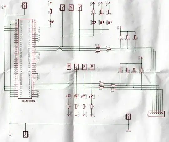
Below is the schematics of the keypad board:

Schematics

Anarkie
  • 329
  • 1
  • 5
  • 18
  • How are you ensuring that pressing 4 and 6 at the same time doesn't short pins 3 and 5 together? – fru1tbat Jun 11 '14 at 17:48
  • @fru1tbat Can you elaborate short a little bit more? Without uploading my code when the board has nothing on, I connect pin5 to the ground, then pin5 LED is on then I press "6" pin7 LED is ON later I press "4" and "6" at the same time this time pin3 LED is on and pin7 LED is still ON. – Anarkie Jun 11 '14 at 17:56
  • @Tut you mean I should use pull-up for rows and pull up for columns? I can't modify the circuit. Also didn't understand much from your comment :( – Anarkie Jun 11 '14 at 21:01
  • To be more complete, I'll provide an answer. It would be helpful if you could provide a schematic showing resistors, LEDs, column drivers and any inverters or transistors that may be in the circuit. Are the 4 rows and 3 columns connected directly to a CPLD or FPGA? – Tut Jun 12 '14 at 10:19
  • @Tut The keypad isn't directly connected to the FPGA there is another board in between, for connecting various boards to the FPGA and I added the schematics. – Anarkie Jun 12 '14 at 13:08
  • On the FPGA board, are the 7 signals associated with the keypad (3 column selects and 4 row signals) directly connected to the connector pins (connector 2 on the above schematic)? If that is the case, follow the directions in my answer by using open-drain logic for the column select outputs in your FPGA. – Tut Jun 12 '14 at 13:16
  • Also note in your schematic, all of the LEDs are shown wired backwards. The anodes go to the current-limiting resistors and the cathodes go to the signal lines. The LEDs light when the signal lines are pulled low. – Tut Jun 12 '14 at 13:19
  • @Tut only 3 columns, 4 rows are connected to the FPGA that is what I have in my UCF file and of course the CLK. – Anarkie Jun 12 '14 at 15:16
  • Ok, thanks. I stand by my answer, use open-drain VHDL logic for the column select outputs. – Tut Jun 12 '14 at 15:24

3 Answers3

4

The short answer:

Invert your logic. Drive the column select lines with open-drain (or open-collector) logic where the selected column is pulled low and the un-selected columns are floating. When you look at a row, a key-press will be detected by a '0'. Un-pressed keys will be detected by a '1'.

Now the details:

As EEIngenuity points out, when you press 2 buttons in the same row, it results in a short-circuit between their corresponding columns. This (and other problems involving multiple key presses) is usually overcome in a keyboard matrix by adding a diode in series with each switch.

Since adding diodes is not an option for you, you will need to float the outputs of your inactive column selects to avoid trying to drive them to the opposite polarity as your active column select. This is done using open-drain logic. If your column selects are tied directly to a CPLD or FPGA, you should be able to accomplish this in your VHDL code.

The photo in your question shows that you have a pull-up resistor on each column and each row. The pull-ups on the columns are unnecessary, but will not hurt anything. The pull-ups on each row will assure a high condition unless pulled low by the open-drain driver on the column selects (through a closed switch).

I have had to make some assumptions about your circuit since you have not provided a complete schematic or your VHDL code. You say

when no key is pressed, which is the condition pin4pin6pin7pin2 = "0000"

yet from the photo you provide, pull-up resistors are shown. This implies that you already have a logic inversion somewhere, possibly in your VHDL code or (less likely) inverters between your rows and your logic device (CPLD or FPGA).

Edit:

Per your comment, you are using negative logic in your descriptions: "0000" indicates all four pins are high, etc. That being the case, assuming the column selects and row signals go directly from connector 2 on your schematic to the FPGA, just follow my directions above by using open-drain logic for the column select outputs in your FPGA.

I am not a VHDL expert, but I found this from Xilinx:

Infer the open drain buffer by using the following code:

VHDL:

dout <= 'Z' when din='1' else '0';

Also note in your schematic, all of the LEDs are shown wired backwards. The anodes go to the current-limiting resistors and the cathodes go to the signal lines. The LEDs light when the signal lines are pulled low.

Tut
  • 4,195
  • 1
  • 21
  • 38
  • I'm about to scan the schematics installing the scanner driver – Anarkie Jun 12 '14 at 11:27
  • You are right about `pin4pin6pin7pin2 = "0000"` no key press is actually `1111` . In my question 1s should 0, 0s should be 1s, I tried to crypt the question a little bit, sorry for that if it caused misunderstandings... – Anarkie Jun 12 '14 at 12:07
  • I added the schematics. – Anarkie Jun 12 '14 at 13:09
  • thanks a lot for your explanations, after reading your answer I have some ideas but first what do you mean with "columns are floating" , "need to float the outputs" , by float do you mean : 110, 101, 011 ? This I am doing already, actually in my code when a key is pressed all other keys should be ignored I just don't understand how the LED turns off and pin7 becomes high(1), while code is running. Anyway if I understood correct is your solution suggesting while Im scanning pin5, output ports "110", I should have `out <= 'pin3' when din='1' else '0';` – Anarkie Jun 12 '14 at 15:38
  • 1
    Look at the link I provided: [open-drain (or open-collector)](http://en.wikipedia.org/wiki/Open_collector). The active column is selected by driving 0V on that column line. The inactive columns should NOT be driven with 3.3V on that line, but need to be floated (put into a high impedance state) which effectively disconnects those lines from the circuit. If you try to drive them to 3.3V, the short-circuit created by pressing 2 buttons in the same row at the same time, will cause a contention between one trying to drive low and the others trying to drive high. – Tut Jun 12 '14 at 15:56
  • What I am suggesting is something like: pin3_out <= 'Z' when pin3_internal = '1' else '0'; ... The 'Z' specifies that the output is floated (not driven) when your internal logic is '1' – Tut Jun 12 '14 at 15:58
  • `pin3_internal` is going to be an output port probably, and it isn't possible to read output ports in VHDL. Also what is "Z" ? A bit signal? I don't understand that `when` case the normal one I know is like : `output <= in0 WHEN "00",` – Anarkie Jun 12 '14 at 16:36
  • I called it pin3_internal so you wouldn't get it confused with your output pin which I called pin3_output (pin3_internal is NOT an output pin, but comes from your internal logic). As I said, I'm not a VHDL expert. I normally code in Verilog. My example came from Xilinx. 'Z' is a valid value (High Impedance) in VHDL for [std_logic](http://www.cs.sfu.ca/~ggbaker/reference/std_logic/1164/std_logic.html). I think you may need to study your VHDL. I don't think I can explain it any better. – Tut Jun 12 '14 at 16:47
  • I did some more research about open collector, and this definetely is the answer to my problem but yet I still don't know how to implement it, I also understand now the code `pin3_out <= 'Z' when pin3_internal = '1' else '0';` if it had paranthesises I would understand faster :) This means when I'm checking `pin5` I should float `pin3` and `pin1`, so I think I should do this at the same line where I'm setting `pin3pin1pin5 <= "110"` and `pin3_internal` here `pin3_out <= 'Z' when pin3_internal = '1' else '0';` isn't any of the pin2,pin7,pin6,pin4? Where should I `pin3_internal` and work ? – Anarkie Jun 14 '14 at 16:45
  • After trying few variations I found it out, thank you zillions you are a legend =) open collector code you gave worked! – Anarkie Jun 14 '14 at 17:45
  • Now I'm writing a documentation about my circuit, I should also mention this solution, is pin7 going directly to ground when pin3 and pin5 have VDD at the same time?We solve it with inverting pin3 stopping the Voltage flow, did I understand correctly? This method is called open-collector, used for pull-up resistors? If it was pull-down 1 would be high in our case and we would need `dout <= 'Z' when din='0' else '1';` I know you wrote a lot but would you please elaborate the solution a little bit more for me? – Anarkie Jun 15 '14 at 09:51
2

Since you are using VHDL and you have an asynchronous input, I'm writing this answer to ensure you took a precaution. I'm not sure if this is your issue but it very well could be.

See a question I asked some time ago: VHDL: receive module randomly fails when counting bits

Now, you say that:

Because "0000" is detected as a no key pressed, the state machine jumps from state to state. While holding 4 and 6 if one pushes and leaves 4 several times, it is detected as 6 pressed several times, which is a big bug.

Which is somewhat similar to what I was facing. I had an issue where my state machine would skip states, which seemed impossible.

If you read the answers to the question linked above, you'll see that it is recommended to add a synchronizer to the input line before it is fed into your state machine. This is typically accomplished with two D Flip Flops in series:

enter image description here

Not having your button input synced with your HW causes very bizarre issues, which I've experienced with my N64 project. Adding this little bit of HW was almost like magic.

So please check first that your inputs are being synced.

Nick Williams
  • 1,815
  • 3
  • 17
  • 29
  • To implement the Synchronizer on the answer doesn't seem to be difficult but when I read the process, what I understand is that `async_in` is delayed with 3 clock cycles but its value and everything is the same? – Anarkie Jun 11 '14 at 18:48
  • The big difference is that your signal will be converted from asynchronous to synchronous. What happens in HW sometimes with asynchronous signals (like your buttons) is that the bits are in "meta-stability", this causes very strange errors in the HW. Using the D Flip Flops ensure that meta-stability does not occur in your design. I was also skeptical of the effectiveness of this, but it solved my issue perfectly. – Nick Williams Jun 11 '14 at 18:52
  • I tried it, was worth a try but didn't help :( – Anarkie Jun 11 '14 at 19:14
1

This is an interesting question! The reason you are seeing a low on pin7 when you press key4 and key6 is because of pin3 and pin5.

To explain further, pin3 and pin5 will never be high at the same time - one of them will always be a path to ground (according to your design). Thus, when you press key 4 and key 6, you are creating a path to ground for pin7.

See image:

Pin 7 sees a path to ground. You have a short circuit.

  • I added a picture to my question and pin7 looks high still when both keys are pressed. – Anarkie Jun 11 '14 at 18:22
  • OP explained that he does not raise pin 3, 1 or 5 HIGH at the same time at any moment. He sequences the columns with: "001", "010", and "100. Pins 3 and 5 are never HIGH simultaneously to begin with. – Nick Williams Jun 11 '14 at 18:22
  • 1
    That's the point @EEIngenuity is trying to make - there's an apparent path between pins 3 and 5, which will never have the same value, "thus, when you press key 4 and key 6, you are creating a path to ground for pin7." – fru1tbat Jun 11 '14 at 19:38
  • @fru1tbat But as you see on the picture I uploaded, pin7 is on and it doesn't go to ground? But lets say it does go to ground, then it will be impossible to overcome my problem? – Anarkie Jun 11 '14 at 20:23
  • "While holding 4 and 6 if one pushes and leaves 4 several times, it is detected as 6 pressed several times, **which is a big bug**." This sounds like you aren't detecting 'no keys pressed' between valid key detections. –  Jun 12 '14 at 00:10
  • @Anarkie In your new picture, would you happen to know if those respective LED's are wired: (a) _series between the button and the gold terminal_ **or** (b) _parallel between the terminal and ground_? Since the gold terminal is floating and the LED's still light up, it would seem that those LED's are sitting in parallel between the switch and ground. That might be why they still light up during this input combination. – Miron Veryanskiy Jun 12 '14 at 07:21
  • @EEIngenuity I added the schematics. – Anarkie Jun 12 '14 at 13:08
  • @Anarkie, As Tut mentioned in his answer, the LED's are absolutely drawn backwards in the schematic. But they are in fact tied to the node in parallel. The "no code uploaded" trial operates properly. Have you tested for the short-circuit event that I suggested in my original answer? If so, how did you do it? – Miron Veryanskiy Jun 12 '14 at 18:09
  • The test I did for the short circuit event is pressing 4 and 6 at the same time as you see on the picture, else I don't know what you mean. – Anarkie Jun 12 '14 at 19:34
  • 1
    @Anarkie In the picture Pin3 is not connected to GND or VDD. It is a floating node. This does not create the short-circuit scenario that you have in your original trial. Try to connect pin 3 to VDD and Pin5 to GND and repeat this test. – Miron Veryanskiy Jun 13 '14 at 20:20
  • 1
    @EEIngenuity You are absolutely right!!! Yes, yes when I connect pin3 to VDD, pin7 becomes low!!! So please help me how can I overcome this problem and make it work :( I'm using VHDL and also another colleague who is in the same project in a different team, doesn't face this problem so somehow he solved it but I don't know how, same keypad, same board! – Anarkie Jun 14 '14 at 12:36