2

I want to drive an DC motor with ability both to change direction, and torque. Obvious solution: PWM + H-Bridge. I've been planning to use a PSoC4 for controller, and L293DNE for the H-bridge, which seems like a pretty standard choice. I've been pondering choosing some circuit to drive power supply with PWM, but reading the L293DNE datasheet, I saw it has 'Enable' pins - 1,2EN, 3,4EN.

enter image description here

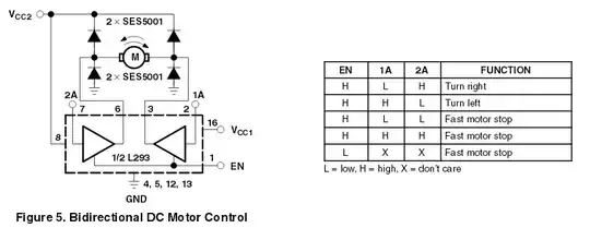
Can I just drive the EN pin with PWM signal to achieve variable torque/speed, or will that cause problems, e.g. faster overheating or something like that? Are there other caveats I should consider (e.g. 'fast motor stop' instead of just 'power disconnected' resulting in some weird dutycycle:torque curve?) Should I add some more circuitry besides what's pictured if I drive 'EN' with PWM?

SF.
  • 1,108
  • 2
  • 15
  • 27
  • 1
    Read this regards choice of H bridge - you might find it isn't good enough for your application http://electronics.stackexchange.com/questions/108686/what-h-bridge-drivers-are-preferred-for-applications-controlling-a-low-voltage-m BTW I wouldn't use EN for PWM -the A inputs are reserved for PWM. – Andy aka Jun 10 '14 at 09:51
  • @Andyaka: I'll be working with 12V or thereabouts (can supply more to get full 12V on output), so I don't worry about voltage losses. Choosing which output (1A,2A) to drive with PWM may add unnecessary complexity (I want to keep direction and torque separate), but if that is the correct approach, well, I'll take it. – SF. Jun 10 '14 at 10:20
  • 1
    Are you sure you're making the right decision. At 2 amps, the volt drop will be about 3 volts and that's a hefty 6 watts power dissipation in the H bridge. Your choice dude. – Andy aka Jun 10 '14 at 10:28
  • Your question asks about driving an AC motor, but the sample diagram you show is for a DC motor. Which is it? – Dave Tweed Jun 10 '14 at 10:52
  • 1
    @Andyaka: I'd rather go with higher voltages and not exceed the 1.2A the chip is rated for, also, DIP form factor is quite important for me (will be using breadboards before I have a working circuit. – SF. Jun 10 '14 at 10:52
  • @DaveTweed: Whoops, my mistake. Meant DC of course. – SF. Jun 10 '14 at 10:53

3 Answers3

2

Don't know if something has changed but the current datasheet indicates that when EN is low that it is a "free running" stop, not a fast motor stop. It also is indicating that for each half bridge, the output is highZ, when EN is low Also, the transition time for going H->L or L->H is 300ns. Seems like it should work now?

1

You will experience some significant performance issues if you were to use the EN for PWM.

If you look at the datasheet, especially the part you provided in the OP:

enter image description here

the EN pin doesn't just stop sourcing/sinking power (ie the FET's are not gated), it creates a "Fast motor Stop" condition which basically means BothTop or BothBottom switches are enabled. This essentially shorts out the machine windings and it rapidly stops the rotor.

As a result if you were to use such a pin for PWM you would be continuously stopping

  • So what signal set (EN, 1A, 2A) should I output for "PWM Low"? Say, I want to turn right at 50% torque. For 50% of the time I output EN=1, 1A=0, 2A=1. What should I output the remaining 50% of the time? – SF. Dec 07 '14 at 23:25
  • Unfortunately for this configuration you cannot just PWM. As you do not have exclusive access to all 4 high&low switches there is no way not produce a "fast motor stop" situation. If you need to use this chip in this arrangement the only alternative would be to provide a form of chopper on the main rail and use that for PWM torque control and this chip purely for direction –  Dec 07 '14 at 23:35
  • Bummer. So probably I should just go with a different chip than L293. What type of output should I look for - how is the output state right for PWM low (FET's not gated) called? ...eh, I guess I could still PWM the Vcc2, or even the GND of the chip... eh, I wonder what kind of noise nightmares would it create... – SF. Dec 07 '14 at 23:44
  • Well... You might be able to actually. If you were to generate a signal and send it to 1A & send the inverse to 2A. If you then PWM these... 50% duty should produce an average of zero volts at the terminals. Increase the duty will increase the average voltage to one leg --> increase in voltage & thus current –  Dec 08 '14 at 00:39
  • Wouldn't reverse polarity produce even more braking torque than shorted terminals? – SF. Dec 08 '14 at 01:08
0

The part you've linked to is rated at 70 degC and has an absolute maximum current rating of 600mA continuous. At this current you are going to be dissipating about 1.6 watts typically (2.6 volts dropped on the transistors x 0.6 amps).

The "N" package has a thermal rating of 67 degC per watt. The DNE package isn't specified - it says "TBD" and this usually means it's worse. With a continuous current of 600mA the device will warm up over 107 degC.

Regards the PWM input. A and B are the recommended inputs for the rapid changing required when using PWM - the spec gives propagation delays and rise/fall times - these are not quoted for the enable pin as far as I can see.

Andy aka
  • 434,556
  • 28
  • 351
  • 777
  • ...a matter of good heatsinks. The target application will have a plenty of heat-sinking volume. – SF. Jun 10 '14 at 11:32
  • @SF. Good luck dude and have a fire extinguisher to hand! – Andy aka Jun 10 '14 at 11:41
  • The chip has built-in thermal shutdown. – SF. Jun 10 '14 at 11:46
  • @SF. I know it has but how much current does your motor take and how long will you expect it to run for? – Andy aka Jun 10 '14 at 11:51
  • I believe it will operate at 10% of max speed for 90% of the time, with only brief "spikes" where achieving full speed or full torque will be important. I'd prefer it to have a 'motor idle' setting instead of 'fast motor stop', which would significantly reduce power output required (I can always switch polarity for rapid braking) but I'm not sure it's easily attainable in H-bridges. – SF. Jun 10 '14 at 12:01
  • So what current will the motor take on full power and how long does full power last. – Andy aka Jun 10 '14 at 12:55
  • I'm not sure yet - this will depend on mechanics which are not decided yet - but I expect semi-frequent ~0.1s pulses of "changing direction" roughly in 1s timeframe (high torque but low speeds) and transfer between work areas at full speed - 3-4s every minute or so. – SF. Jun 10 '14 at 13:26