9

I have a battery pack that I would like to use as a source for all of my battery powered components on a commuting bicycle.

My pack includes (10) 1.2V cells wired in series:

{[+ -][+ -][+ -][+ -][+ -][+ -][+ -][+ -][+ -][+ -]}  
|                                                  |
└--------------------- 12 V -----------------------┘

The issue is that some of my devices operate with (2) AA batteries, some take (4), and some that require 12V. What I would like to do is:

  • wire all devices to one one common pack, eliminating the need for individual batteries, and simplify recharging
  • use a robust design, resistant to vibration and weather
  • use appropriate design for low amperage components
  • supply all the components at virtually 100% efficiency
  • easy to service (i.e. periodically identify and replace bad cells)

From all the research I can find, there appears to be two common solutions:

1) add off-the-shelf electronic DC-to-DC converters to bring voltage down to 6V and 3V respectively, and accept the conversion inefficiency.

2) splice the series at specific points to create three circuits.

{[+ -][+ -][+ -][+ -][+ -][+ -][+ -][+ -][+ -][+ -]} 
|         |              |                         |
└- 2.4 V -┘              |                         |
|                        |                         |
└-------- 6 V -----------┘                         |
|                                                  |
└--------------------- 12 V -----------------------┘

3) a third option is to just live with the extra weight. Power each component separately and independently, and recharge/replace batteries as needed.

Each of these options has its disadvantages. But #2 seems to be the most promising. The most obvious problem is that load is unevenly distributed among the cells in the pack. If I could overcome that, then I think we have a winning solution.

So my question is this:

Is it possible--using clever wiring and minimal electronics--to supply three different voltages from the same pack of NiMH rechargeable batteries?

Comments, suggestions and ideas are all appreciated.


My best guess so far is the following:

  • combining a timer and relays to make essentially a double-pole, five-throw switch that will cycle through each pair of cells every minute or so, providing a steady stream of 2.4v
  • combining a timer and relays to make essentially a double-pole, double-throw switch that will cycle through half of the cells every minute or so, providing a steady stream of 6v
  • connecting all 12v devices to the pack like normal

Unfortunately, I'm stuck on the relays, and how to connect the timer to trip the relays, all while maintaining three independent circuits. I'd also like to keep things compact. It is not practical to having a shoebox-sized circuit board in addition to the battery pack. Ideally I would like to pack everything into a Pelican 1010 waterproof case.

At first I thought I could just use diodes and connect everything in one great big mass, but I abandoned that option after some earlier testing. It appeared that the diodes were getting awfully hot, which of course means they were dissipating a lot of energy that was supposed to go to the components.

Another alternative I've considered is a Zener diode voltage regulator. This would pair well with a low amperage application and minimal electronics, but unfortunately it also suffers from conversion inefficiency.

For the record, my components are:

+---------------------------+---------+--------------+-------+  
| component                 | voltage | usage        | draw  |  
+---------------------------+---------+--------------+-------+  
| tail light                | 3V      | night time   |  25mA |  
| headlight                 | 6V      | night time   | 250mA |  
| cycling computer          | 3V      | always       |   1mA |  
| turn signals (automotive) | 12V     | intermittent |  55mA |  
+---------------------------+---------+--------------+-------+  

The good news is that since all of these devices are battery operated, they tolerate the normal voltage fluctuations of battery chemistry.

Future plans:
6v hub-dynamo recharging system
Ricardo
  • 6,134
  • 19
  • 52
  • 85
LeftyMaus
  • 193
  • 1
  • 5
  • I wonder why you do not using 6 V lights for tail and turn signals. This would simplify design a lot. – Vovanium Jun 06 '14 at 13:10
  • I am very pleased with my tail light, the [Cateye TL-LD1100](http://www.cateye.com/en/products/detail/TL-LD1100/) It is exceptionally sturdy, and by far the best I have found on the market. Unfortunately, I cannot find any bicycle turn signal system that is rated 6v, so I had to make my own. Again using sturdy parts the best I could find is LED-automotive relay [EP-34](http://www.ledlight.com/electronic-led-flasher-ep34.aspx) and Truck [marker lights](http://www.monsterlights.com.au/marker.htm). Both rated 12v. – LeftyMaus Jun 06 '14 at 14:02
  • It is not so difficult to make LED light on your own and install it in enclosures you chose. There are also lots of simple flashing circuits you can build (e. g. just three parts with ICM7555 CMOS timer IC). – Vovanium Jun 06 '14 at 14:14
  • I found Truck marker lights could be very easy to change rated voltages by replacing of current limiting resistors. There are two LEDs and two resistors on board, so it seem they power single LED with series resistor with 12 V (with 20% of efficiency). – Vovanium Jun 06 '14 at 14:25
  • Another advantage of these particular marker lights is that they are ultrasonically sealed (weatherproof). They are also very light, which reduces vibration stresses. I have them mounted on the fork and seat-stays, so they get punished regardless whether I'm on smooth roads or rough. I am reluctant to open them up because I am not confident I will be able to re-seal them again. – LeftyMaus Jun 06 '14 at 14:35
  • Did you try powering them with 6 V? It may appear they light just a bit dimmer. – Vovanium Jun 06 '14 at 14:46
  • That is exactly what they do. I was planning on using this phenomenon to my advantage by creating running lights at 6v that would always be on, and then when I flick the turn signal light, it would connect 12v power and the lamps would be at full brightness on every blink. – LeftyMaus Jun 06 '14 at 14:53
  • You can get off-the-shelf 12V to 6V switching regulators for a few $/£. They're a small PCB. Then you could run a 3V (or 3.3V) linear regulator (a single component) off the 6V line to give the 26mA max @3V. It's not worth a 2nd switcher for such a small load. All you have to do is wiring, no real electronics. If you get a variable switching regulator it might be worth trying all the 3-6V components at 5V - if they're not *too* expensive. – Chris H Jun 06 '14 at 18:40

2 Answers2

12

You should use DC-DC converters or dedicated battery packs for every voltage.

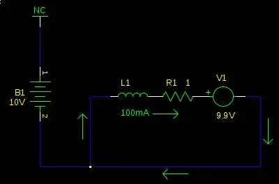
You should not use middle points of battery packs. This lead to different charge levels in cells. As a result you'll get an inverse voltage on cells which are discharged first and this will damage the battery and possibly the equipment.

Schematic below shows this.

Inverse voltage is appearing when one of the sells in a battery is completely discharged thus have no voltage across it. If other cells continue to deliver the power, current will still flow thus 'charging' the dead cell with negative voltage.

Load connected to the dead cell this way get reverse polarity supply voltage, thus, possibly, die.

schematic

simulate this circuit – Schematic created using CircuitLab

Most optimal (if you do not want to use other voltage rated devices) I think is to supply the most powerful device (6V headlight) directly and use step-up/step-down converters for all others.

Vovanium
  • 987
  • 8
  • 10
  • What do you mean by "elements"? What is going to get "different charge" or "inverse voltage"? The cells that make up the battery pack? Or the components of the lighting system, i.e. tail light or headlight? – LeftyMaus Jun 06 '14 at 14:27
  • Elements are sells. Sorry for bad english. I'll improve my answer – Vovanium Jun 06 '14 at 14:28
1

Stemming off what Vovanium suggested, look at something known as a Voltage Doubler, or charge-pump. I did quick search around and found that integrated circuit package that seems somewhat fitting for your applications - specifically the low quiescient current (110uA) and conversion efficiency (98%). The datasheet indicates this particular IC has a maximum output current of 45mA, so you'll have to find something that can supply a little more current, but I just wanted to make you aware of this option.

These are, of course, DC-DC converters anyway so it's essentially the same thing. It might be just as easy to do with a step-up (charge-pump) and a step-down (chopper) for your application.

Perhaps just a couple of these converters would do. You could boost 6V to 12V and buck 6V to 3V for your needs. It is written in the datasheet these devices have the capacity of providing up to 20W.

sherrellbc
  • 3,431
  • 6
  • 35
  • 62