4

Generally speaking, what time of signals should be designed to have a 50 Ω trace impedance ?

Some datasheets I've read have specifically mentioned 50 Ω but others have not.

Is it good practice to make every trace 50 Ω ? Should it be reserved for high frequency communication lines only ? UART ? USB ? SPI ? etc..?

Josip Medved
  • 585
  • 5
  • 8
efox29
  • 11,827
  • 9
  • 56
  • 102

2 Answers2

12

When to consider a digital signal fast enough to treat the interconnect (PCB trace) as a transmission line depends on two things:

  • Electrical length of the signal
  • Rise/fall-time (which is another way to say frequency content)

As a rule-of-thumb(*) whenever the electrical length of the trace is longer than some fraction of the rise/fall time, you will see reflections unless properly terminated. You can use 1/3 to 1/5 for the "fraction".

As an example: 4"/100mm trace is about 700ps of electrical length (use your favorite 2D field solver to find the exact number). If you launch a signal out of a semi-modern FPGA with say 300ps rise-time down that trace, you are sure to get reflections unless termination is used. In this case 1/5 of the rise-time is 60ps and the max trace length without significant reflections is about 8-9mm.

Make sure that you understand that the frequency of the signal is irrelevant. Reflections can happen with a 1Hz signal or a 500MHz signal - it's the same mechanism.

Now you can easily avoid reflections on a longer trace by using series or parallel termination. That is what we mean when we say treat the trace as a transmission line.

And you can easily do this with any impedance. There is nothing magical about 50R. That said, almost all modern digital signals can be routed in 50R and it's a lot easier to deal with only one impedance on any layer in a multilayer PCB.

As to your question about best practice: On boards connecting two or more modern digital parts, all traces are analyzed for signal integrity and routing rules are created before layout. In 99% of the cases I have analyzed, 50R is selected as trace impedance - even for differential pairs like USB, PCIe etc.

(*) Be careful with rules-of-thumb. Technology changes fast enough that you have to understand this stuff or you risk using an outdated rule-of-thumb.

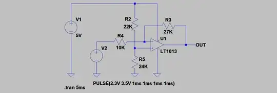
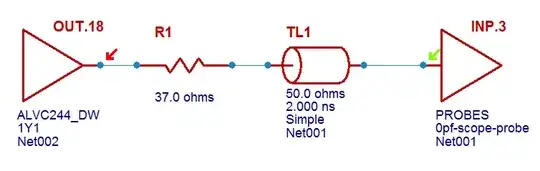
Just for the fun of it I ran some simple simulations for you in Mentor Hyperlynx. Here is the simple circuit:

enter image description here

Here is what happens if you do nothing (note the length of the trace/transmission line here is 2ns or roughly 1ft/30cm):

enter image description here

If we make the trace 60ps long (8-9mm) the reflections are almost gone:

enter image description here

Changing the impedance to some other value does not significantly change this picture. But if we want to use series or parallel termination, we need to know the trace impedance.

Lastly let me just show how it works with a series termination resistor. In this example, the series termination resistor is selected so the output impedance of the driver IC plus the series termination resistor matches the 50R of the trace:

enter image description here

The simulation comes out like this looking very nice even with this long trace:

enter image description here

Rolf Ostergaard
  • 4,448
  • 18
  • 24
4

Fast signals should have their traces considered for transmission lines. 'Fast' depends on the frequency and the length of the trace. For me, if it's over 5MHz, on a regular sized PCB, I'll start making sure I'm not going to get any funny stuff. I'm sure some people will point out problems with that.

Transmission lines with components designed for 50Ω characteristic impedance should use 50Ω traces. Some things have different characteristic impedances, so no, it's not good practice to make everything 50Ω impedance.

By the way, as an aside, 50ohm is hard to read. If you want to type the 'Ω' symbol, in Windows, hold the alt key and type 234 on the num-pad.

Samuel
  • 11,811
  • 31
  • 51
  • Look at rise-time, not frequency. See also my answer. – Rolf Ostergaard Jun 06 '14 at 05:55
  • @RolfOstergaard I can't say I agree with you when you say the frequency is "completely irrelevant". The frequency is highly correlated with set-up and hold times in digital communications. Still, thanks for letting us know you have an answer too and for the additional information in it. – Samuel Jun 06 '14 at 06:17
  • @Samuel Hmmm... Setup and hold times are not related to transmission lines, reflections and termination. This is parameters of digital inputs - not how the electrical signal happens to get there. Setup/hold is not related to the frequency of a signal connected to that input. You can have 100ps setup/0ps hold time on an input and connect it to a 1Hz, a 100MHz or a completely aperiodic signal just fine. – Rolf Ostergaard Jun 06 '14 at 08:59
  • @RolfOstergaard You've missed my point, they're related to whether you care if there are reflections or not. Do you care if an edge rings for 3 ns on a 9600 baud UART bus? Or are you unable to tell because frequency is "completely irrelevant"? – Samuel Jun 06 '14 at 18:45
  • @Samuel - In this, Rolf is more correct than you . Let's say you have a digital link which can operate at a 100 MHz bit rate. Obvously, you'll want ringing to last no more than 10 nsec, and perhaps less (or even much less) depending on the details of timing. BUT if you use that link to send a single bit at a 1 Hz rate, you still need the same short ringing, or you risk mistaking it for a 2 bits (or more, in really pathological cases). So, just "the frequency" of a particular signal is irrelevant. Sort of. Ringing is excited by rise and fall times. – WhatRoughBeast Jun 06 '14 at 19:57
  • @WhatRoughBeast Yes, fair enough, though I don't think we're arguing mutually exclusive points. My point was that frequency is not "completely irrelevant". – Samuel Jun 06 '14 at 22:16
  • @Samuel You are right in that we are likely to have shorter rise/fall times for signals in systems with higher frequencies. The dangerous thing here is that even slower clock speed systems can have very short rise/fall times. I removed "completely" from that sentence. – Rolf Ostergaard Jun 07 '14 at 05:16
  • Samuel and @WhatRoughBeast: I may very well care if a UART bus has reflections. Say if the signals between a UART level shifter and a CPU looks like in the first simulation, absolute maximum ratings of the receiving IC input may well be exceeded (typically -0.3V to Vcc+0.3V). This can be a problem at any bit rate. You would be surprised by how many JTAG chains, I2C busses, SPI busses etc. I have troubleshooted SI issues on for my clients. They all look so slow and innocent - but the rise/fall times may not be... BTW: A UART bus should not have setup and hold times - it's asynchronous. – Rolf Ostergaard Jun 07 '14 at 05:23