14

I'm designing a totem-pole by BJTs in order to drive a MOSFET. I studied on several online examples and built up my circuit according to what I understood from them. However, there is a detail which got stuck in my mind. I would like to know why doesn't shoot-through occur in this circuit during the transition time of the clock pulse (e.g.; when \$V_{clk} \tilde= 6V\$)? In other words, why doesn't the two BJTs become turned on at the same time during the transition?

schematic

simulate this circuit – Schematic created using CircuitLab

Simulation result:
enter image description here
(Vtp and Vgs overlap.)

hkBattousai
  • 13,913
  • 31
  • 114
  • 190
  • Please, could you to supplement the question, adding a plot to Vb (right side of R2)? To facilitate you can remove the plot to Vclk and include that. My suggestion is to investigate the behavior of the base voltage (saturation or not for QH transistor, for example). I did not do the simulation, but from what I could verify visually, the Vce voltage, when Vclk high, is aproximadamete 0.125 V. – Dirceu Rodrigues Jr Jun 02 '14 at 15:16
  • 3
    @DirceuRodriguesJr Unfortunately, no. CircuitLab doesn't let me edit the circuit. It shows a flier as soon as the schematic window opens, saying something like "Thank you for using demo. Now you have to pay us for further usage.". – hkBattousai Jun 02 '14 at 17:04

2 Answers2

15

These transistors don't conduct unless Vbe>0.6V for the NPN, Vbe<-0.6V for the PNP. And as the bases and emitters are tied together, it is impossible for both these conditions to be true at the same time. So when one transistor is turned on, the other is turned off.

HOWEVER

if R2 is too low, the transistor being turned on will "saturate". And when saturated, it will take a significant time to turn off after the base current is removed. This question and answers discuss one famous solution to that problem.

However the present value of R2 limits the base current, because the voltage across R2 will be relatively low, so the transistors will not saturate hard and will turn off relatively fast.

  • 6
    Saturation is no issue here. Since the transistor that is turning off will have one B-E drop negative bias applied to it when the other starts to turn on. That will turn the transistor off quite quickly, even if it was in saturation. In any case, the bases can't be driven past the collector voltage, and the base current will always be only what is needed to sustain the emitter current. These transistors can't saturate in this configuration, with R2 having nothing to do with it. Low Ro can cause problem, but not really a saturation recovery problem. – Olin Lathrop Jun 02 '14 at 12:30
  • 4
    Also, keep in mind that with a capacitive load like this, there's a lot of current flowing just after each transition, but essentially zero current just before the next one. There is not a high concentration of charge carriers that needs to be dissipated in the transistor that's turning off (even if R2 has a low value). – Dave Tweed Jun 02 '14 at 12:43
  • 1
    Two very good points negating the importance of saturation for this specific configuration (Vbe cannot exceed Vce if you assume they are fed from the same supply, and the capacitive load. –  Jun 02 '14 at 12:57
14

In a true totem pole configuration, shoot thru usually does occur for a very short time during switching.

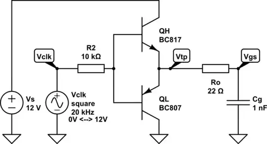
However, what you have is not a totem pole configuration. You have two emitter followers back to back. In this case, you will not get shoot thru. For each transistor to be on, the base has to be one junction drop towards the collector voltage from the emitter. Your double emitter follower therefore has a 2 junction drop (about 1.2-1.4 V) deadband over which neither transistor will conduct.

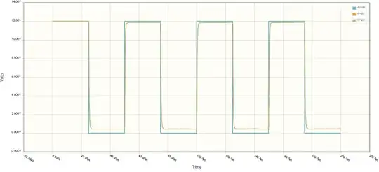
For example, let's say Vtp is 6 V and that each transistor needs at least 600 mV B-E voltage to turn on in a meaningful way (actually -600 mV for the PNP, but this is implied in this case). That means when the right side of R2 is in the range of 5.4 to 6.6 V, both transistors are off. If this voltage goes above 6.6 V, the top transistor will start to come one, which causes current to flow out of its emitter, which raises Vtp to be 600-700 mV below the driving voltage. The same works with opposite sign for the bottom transistor. When the driving voltage goes below 5.4 V, the bottom transistor starts to conduct and sink current thru its emitter, which in turn pulls Vtp low to stay 600-700 mV below the driving voltage.

Olin Lathrop
  • 310,974
  • 36
  • 428
  • 915
  • 3
    As a matter of fact, the configuration shown here, even if complicated with emitter and collector resistors, is a well-known source of distortion when used in audio amplifiers, because it has a "dead zone" around zero. The solution is the AB-class amplifier. – WhatRoughBeast Jun 03 '14 at 01:31