With the recommended current through it, it's possible for an LED to drop a minimum forward voltage (Vf), which should be the the voltage used to calculate the value of the current limiting resistor, the reason being that with that resistor in place - and a fixed supply voltage - the current through the LED can never exceed the 20 mA design target.
That being the case, the value of the series resistor for the red LED would be:
           Vs - Vf      3.7V - 1.8V
     Rs = --------- = -------------- = 95 ohms
             If            20mA
95 ohms isn't an available standard 5% value, but 91 ohms and 100 ohms are, and bracket 95 ohms.
Then, for the current through the 91 ohm resistor we have:
         Vs - Vf     1.9V
    If = --------- = ------ ~ 21 mA
           Rs        91R
and for 100 ohms:
         1.9V
    If = ------ = 19 mA
         100R
Since the LED is rated for a maximum current of 30mA, either resistor will limit it to less than that, so either is safe.
As for the resistors themselves, the 91 ohm resistor will dissipate:
P = (Vs - Vf) * If ~ 40 milliwatts,
while the 100 ohm one will dissipate about 36 milliwatts, so a +/-5%, 1/10th watt (or larger) resistor would work OK for either.
The calculations for the green and blue LEDs are identical except for the Vf's, so they won't be repeated here.
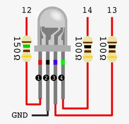
As an aside, you mentioned that you'll be using four tricolor lamps, so you'll need to use three separate resistors for each lamp, or a total of 12 for the array.
Also, note that if you want to drive the LEDs to maximum brightness by putting 30mA through them, if your resistor values come out unobtainium you'll have to bump the values up in order to keep from overdriving the LEDs.