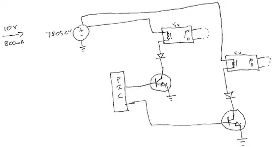
Assuming you are using the 5V versions of the family of relays you've linked (005-360), the coil resistance is between 62.1 and 75.9 ohms. Under 5V, that's 81mA each, so you shouldn't have any problem powering 5 of these (403mA) on the current limit side: the 7805CV is internally limited to 750mA typical (1.2A max).
However, depending on your casing, the temperature overload protection might activate: for a T0-220 for example, the thermal resistance junction to ambient is 50°C/W and you're dissipating 5V x 400mA with 5 of them which yields a temperature increment of 100°C with respect to ambient. The thermal resistances are approximate, so that might put it beyond the 150°C limit (which also may be set lower).
Nonetheless this is for 5, it should not be a problem for 3 except if the thermal limit is really lower than operating range. If you want to add a current limiting resistor, beware of the pickup voltage which is 3.75V: any less voltage on the coil and it won't be able to pick up the contact. That means the resistor shall not be more than 20 ohms otherwise the voltage divider will leave less voltage for the coil (be sure to use at least >0.25W resistors). But I would suggest first to measure the voltage delivered by the 7805 while touching it briefly (caution, it may burn!). Then make sure that pickup voltage is really 3.75V by gradually increasing the applied voltage in order to select your current limiting resistor.
Also, you're not actually giving 5V, but 4.3V since the diodes are in series. Not only that but they can't fulfill their job which is to allow the current that can't briefly stop in the inductor to loop around: put them in parallel with the coils instead of in series. Otherwise, the coil will resist switch-OFF by producing a massive voltage between its terminals which may damage the transistor, the diode, or even the regulator.