15

In an opamp, feedback on the positive input places it in saturation mode and the output is of the same sign as V+ - V-; feedback on the negative input places it in "regulator mode" and ideally Vout is such that V+ = V-.

  1. How does the opamp change its behaviour depending on the feedback? Is it part of a more general "behavioral law"? [Edit: Isn't it something in the lines of the voltage added increases the error instead of reducing it in the case of + feedback?]
  2. How can we analyse circuits where both are present?

Whoever answers both at the same time in a coherent manner wins a pot of votes.

enter image description here

Mister Mystère
  • 9,477
  • 6
  • 51
  • 82
  • 1
    There is a theorem that describes a general method to analyze circuits with any kind of feedback, is it what you are looking for? – Vladimir Cravero May 30 '14 at 12:30
  • 1
    There is an OUTSTANDING explanation of basic op-amp operation on this site somewhere, I just can't find it. Some of the more veteran members of the site may link it here, so I'll just add this comment: Suffice to say that you're probably thinking of op-amps only in terms of their inputs trying to be equal. It's a bit more nuanced than that. – scld May 30 '14 at 12:31
  • 1
    Yes to both of you, I think general analysis methods rely on a sound understanding of the behaviour of opamps so I want to address both of these. – Mister Mystère May 30 '14 at 12:42
  • 2
    To answer the question, it is necessary to know what is connected to the pos. terminal: An ideal voltage or current source ? Some additional resistors? – LvW May 30 '14 at 12:57
  • 1
    @LvW, it actually isn't necessary since, typically, we assume the input is *driven* by a source. If a voltage source, then \$v = v_S\$. If a current source, then \$i = i_S\$. The result that \$v = -iR\$ or that \$v_o = 2v\$ is independent of these details. – Alfred Centauri May 30 '14 at 14:34
  • 1
    @Alfred Centauri: To me, typically, there is no ideal source, but a real one with any kind of internal resistor. And because the question was "how to caculate" I did ask for some information regarding the source properties. – LvW May 30 '14 at 14:44
  • 1
    @LvW, even if the source has an internal resistance, the result \$v = -iR\$ and \$v_o = 2v\$ *holds*, i.e., one doesn't need details of the source to derive these results. This is fundamental. If, on the other hand, you wish to find \$\frac{v_o}{v_S}\$ rather than \$\frac{v_o}{v}\$, then you would need to account for any internal source resistance. – Alfred Centauri May 30 '14 at 14:50
  • 1
    @Alfred Centauri: Yes - no doubt about it since vo=2v and v=-iR can be read directly from the figure, without any calculation. However, v is the voltage directly at the pos. input, but - for my opinion - it makes much more sense to relate the output voltage to the applied (non-ideal) signal source and NOT to such an "internal" voltage. – LvW May 30 '14 at 15:01
  • 1
    @LvW, there's nothing wrong with that opinion but that result follows immediately from the two fundamental results. Assuming a non-ideal voltage source, \$v = v_S\frac{R}{R - R_S}\$ and, thus, \$\frac{v_o}{v_S} = \frac{v_o}{v}\frac{R}{R - R_S}\$ – Alfred Centauri May 30 '14 at 15:25
  • 1
    @Alfred Centauri: Only now I had a lock on your calculation (see your answer below). Are you aware that the first part of your calculation assumes that there is an ideal voltage source at the non-inv. input? That means - as I habe mentioned at the beginning - we must assume something, unless more information are given. By the way: The circuit is a short-circuit stable NIC. – LvW May 30 '14 at 17:54
  • 1
    @LvW, the first KVL equation is valid always. The assumption that net negative feedback is present places a constraint on the internal resistance of the source but that part is covered in the second part of my answer. – Alfred Centauri May 30 '14 at 21:19

6 Answers6

15

How does the opamp change its behaviour depending on the feedback?

The ideal opamp behaviour itself is unchanged; it is the circuit's behaviour that is different.

Isn't it something in the lines of the voltage added increases the error instead of reducing it in the case of + feedback?]

That's correct as far as it goes. If we perturb (or disturb) the input voltage, negative feedback will act to attenuate the disturbance while positive feedback will act to amplify the disturbance.

How can we analyse circuits where both are present?

As usual, assume there is net negative feedback which implies that the non-inverting and inverting input voltages are equal. Then, check you result to see if, in fact, negative feedback exists.

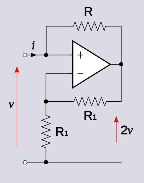
I'll demonstrate by solving your example circuit.

Write, by inspection

$$v_+ = v_o + iR$$

$$v_- = v_o \frac{R_1}{R_1 + R_1} = \frac{v_o}{2}$$

Set these two voltage equal and solve

$$v_o + iR = \frac{v_o}{2} \rightarrow v_o = -2Ri$$

which implies

$$v_o = 2v_+ = 2v $$

This is a good thing because we expect that this is a non-inverting amplifier and indeed, we get a positive voltage gain. Interestingly, the input resistance is negative: \$\frac{v}{i} = -R\$.

However, if we add an additional resistor \$R_S\$ in series with the input, we can run into trouble.

In that case, the equation for the non-inverting input voltage becomes

$$v_+ = v_S \frac{R}{R_S + R} + v_o \frac{R_S}{R_S + R} $$

which implies

$$v_o = \frac{2R}{R - R_S}v_S $$

Note that when \$R_S < R\$, the voltage gain is positive as expected from a non-inverting amplifier.

However, when \$R_S > R\$, the voltage gain is negative for a non-inverting amplifier which is a red flag that something is wrong with our assumptions.

The wrong assumption is that there is negative feedback present and it was that assumption which licensed us to set the non-inverting and inverting input voltages equal in the analysis.

Note that the voltage gain goes to infinity as \$R_S\$ approaches \$R\$ from below. Indeed, there is no net feedback when \$R_S = R\$; the negative and positive feedbacks cancel. This is the 'boundary' between net negative feedback and net positive feedback.


Is this method of picking up on red flags always valid to determine the limit between net positive and negative feedback?

What I did, in this case, was to make an assumption, solve the circuit under that assumption, and check the solution for consistency with the assumption. This is a generally valid technique.

The assumption was, in this case, that net negative feedback is present which implies that the op-amp input terminal voltages are equal.

When we solved the circuit in the 2nd case, we found that the net negative feedback assumption is valid only when \$R_S \lt R\$. If \$R_S \ge R\$, there is no or positive feedback and, thus, no reason to constrain the input terminal voltages to be equal.

Now, it may not be clear why there is positive feedback when \$R_S \gt R\$. Recall the setup for deriving the negative feedback equation:

enter image description here

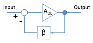
Here, we subtract a scaled version of the output voltage from the input voltage and feed this difference \$V_{in} - \beta V_{out}\$ to the input of the amplifier.

Clearly, this assumes \$\beta\$ is positive in order that there be a difference between the input and scaled output voltages.

The well known result is

$$V_{out} = \frac{A_{OL}}{1 + \beta A_{OL}} V_{in}$$

and, in the limit of infinite gain \$A \rightarrow \infty\$

$$V_{out} = \frac{1}{\beta}V_{in}$$

Comparing this equation with the result for the 2nd case above, see that

$$\beta = \frac{R - R_S}{2R}$$

from which it immediately follows that we have net negative feedback only when \$R_S \lt R\$.


There is some discussion in the comments about the conclusion for case 3, \$R_S > R\$, in the accepted answer. Indeed, the analysis for case 3 is not correct.

As shown above, if we assume the op-amp input terminal voltages are equal, we find a solution where

$$v_o = \frac{2R}{R - R_S} v_S$$

Now assume, for example, that \$R_S = 2R\$ then

$$v_o = -2v_S$$

And, in fact, one can verify that this is a solution where the op-amp input terminal voltages are equal

$$v_+ - v_- = 0$$

However, if we perturb the output slightly

$$v_o = -2v_S + \epsilon$$

The voltage across the op-amp input is perturbed to

$$v_+ - v_- = \frac{\epsilon}{6}$$

which is in the same 'direction' as the disturbance. Thus, this is not a stable solution since the system will 'run away' from the solution if disturbed.

Contrast this with the case that \$R_S < R\$. For example, let \$R_S = \frac{R}{2}\$. Then

$$v_o = 4v_S$$

Perturb the output

$$v_o = 4V_S + \epsilon$$

and find that the op-amp input voltage is perturbed to

$$v_+ - v_- = -\frac{\epsilon}{6}$$

This is in the opposite direction as the disturbance. Thus, this is a stable solution since the system will 'run back' to the solution if disturbed.

Alfred Centauri
  • 26,502
  • 1
  • 25
  • 63
  • Thanks for the clear answer. Is this method of picking up on red flags always valid to determine the limit between net positive and negative feedback? Is the limit that brutal or is there a blurry limit? – Mister Mystère May 31 '14 at 11:24
  • 1
    @MisterMystère, I will work on an addendum to my answer to address your comment later. – Alfred Centauri May 31 '14 at 12:04
  • 1
    @MisterMystère, see the addendum to my answer. – Alfred Centauri May 31 '14 at 18:25
  • Thanks again, that's really an excellent answer. It was really tough to decide which answer to accept, but I went for nidhin's mainly because he could use the reputation (that's a water drop in a lake for you). See you around on SE. – Mister Mystère Jun 02 '14 at 08:55
  • 2
    @MisterMystère: Are you aware that nidhin´s answer is NOT correct in all cases? He wrote:"The output is finite in cas1 and case3 so net feedback is negative in these conditions". Apparently, this is false for case 3. In this case, the circuit is unstable and the result "-2" is wrong. Instead, the opamp goes into saturation. – LvW Jun 02 '14 at 10:41
  • Great catch LvW, I'll ask nidhin to amend his answer and accept my second favorite if he does not manage to do it. – Mister Mystère Jun 02 '14 at 10:59
  • @AlfredCentauri Consider the following possibility: "when \$R_sV_{in}\$. So there is a +ve f/b through R. But the -ve f/b through R1's is more and hence net f/b is negative. But when \$R_s>R\$, the current through R is from left to right because \$V_{out} – nidhin Jun 03 '14 at 04:19
  • @nidhin: I think, your considerations are not correct. You are assuming that the opamp works under linear conditions even for net positive feedback. That´s not OK. By the way: Exactly this is the error introduced by simulation program if an IDEAL amplifier is used. Example: Even with calculations by hand it is possible to show that an opamp with (only) positive feedback can provide gain. Every basic formulas (KVL,KCL) are fulfilled. Nevertheless, in reality the opamp goes into saturation. The error: We assume linear conditions without any disturbance (noise, power switch-on). – LvW Jun 03 '14 at 09:23
  • @nidhin, even with positive feedback, there *is* a valid solution such that the op-amp input terminals have equal voltage. So, if we solve the circuit with that constraint, we will find a solution. *However*, the solution is not stable. Perturb the solution and find that the system 'runs away' from it rather than correcting. – Alfred Centauri Jun 03 '14 at 10:58
  • @nidhin, I've updated by answer to address your case 3 analysis. – Alfred Centauri Jun 03 '14 at 11:39
  • @Alfred Centauri: I know what you mean - however, I doubt if we are allowed to call this solution "valid" because - in practice - it will never be stable. More than that, there will be a contradiction for our case 3: A positive input voltage will cause a negative output voltage. The whole sytem is comparable to a ball which is positioned above another ball. In theory - and without any disturbing influence - this system can be called "stable". However - only as far as mathematics are concerned. Hence, from the engineering point of view I would not consider such a solution as "valid". – LvW Jun 03 '14 at 12:07
  • @LvW, would you prefer "consistent"? – Alfred Centauri Jun 03 '14 at 12:11
  • @LvW and AlfredCentauri what you said makes sense. I was thinking that virtual short exists only at -ve f/b. Give me a little time to think over it. – nidhin Jun 03 '14 at 17:48
  • @Nidhin, while using the term "exist" you have to be careful. The meaning can be twofold: Exist in reality (to be measured) or in theory and under idealized conditions only. It is really interesting (nearly a philosophical question): Performimng an AC analysis (frequency response) for the circuit under discussion having net positive feedback will result in a transfer function (magnitude, BODE diagram) which looks quite "normal". We know that it is not realistic in practice. However the question to be answered is: Is the result right or wrong? – LvW Jun 03 '14 at 18:44
13
  1. Op-amp always behaves as a differential amplifier and the behavior of circuit depends on the feedback network . If negative feedback dominates, the circuit works in linear region. Else if positive feedback dominates, then in saturation region.
  2. I think the condition \$V^+ = V^-\$, the virtual short principle, is valid only when the negative feedback dominates. So if you are not sure that negative feedback dominates, consider op-amp as a differential amplifier. To analyze the circuit, find \$V^+\$ and \$V^-\$ in terms of \$V_{in}\$ and \$V_{out}\$. Then substitute in the following formula, $$V_{out} = A_v(V^+-V^-)$$ calculate \$V_{out}/V_{in}\$ and then apply the limit \$A_v\rightarrow\infty\$
  3. Now, net feedback is negative if \$V_{out}/V_{in}\$ is finite. Else if \$V_{out}/V_{in} \rightarrow \infty\$, then the net feedback is positive.

Example:
From the circuit given in the question, $$V^+ = V_{in}\ \text{and}\ V^- = V_{out}/2$$ $$V_{out} = A_v(V_{in} - V_{out}/2)$$ $$\lim_{A_v\rightarrow\infty}\frac{V_{out}}{V_{in}} = \lim_{A_v\rightarrow\infty}\frac{A_v}{1+A_v/2} = 2$$ $$V_{out} = 2V_{in}$$ \$V_{out}/V_{in}\$ is finite and net feedback is negative.

\$\mathrm{\underline{Non-ideal\ source:}}\$
In the above analysis, \$V_{in}\$ is assumed to be an ideal voltage source. Considering the case when \$V_{in}\$ is not ideal and has an internal resistance \$R_s\$. $$V^+ = V_{out}+(V_{in}-V_{out})f_1\ \text{ and }\ V^- = V_{out}/2$$ where, \$f_1 = \dfrac{R}{R+R_s}\$ $$V_{out} = A_v(V_{out}/2+(V_{in}-V_{out})f_1)$$ $$V_{out}(1-A_v/2+A_vf_1) = A_vf_1V_{in}$$ $$\lim_{A_v\rightarrow\infty}\frac{V_{out}}{V_{in}} = \lim_{A_v\rightarrow\infty}\frac{f_1}{\frac{1}{A_v}-\frac{1}{2}+f_1}$$ $$\frac{V_{out}}{V_{in}} = \frac{f_1}{f_1-\frac{1}{2}}$$

case1: \$R_s\rightarrow 0,\ f_1\rightarrow 1,\ V_{out}/V_{in}\rightarrow 2\$

case2: \$R_s\rightarrow R,\ f_1\rightarrow 0.5,\ V_{out}/V_{in}\rightarrow \infty\$

\$%case3: R_s \rightarrow \infty,\ f_1 \rightarrow 0,\ V_{out}/V_{in} \rightarrow 0\$

The output is finite in case1 and so net feedback is negative in these conditions (\$R_s < R\$). But at \$R_s = R\$, negative feedback fails to dominate.

\$\mathrm{\underline{Application:}}\$
Case1 is the normal working of this circuit but it is not used as an amplifier with gain 2. If we connect this circuit as a load to any circuit, this circuit can act as a negative load (releases power instead of absorbing).

Continuing with the analysis, the current through \$R\$ (from in to out) is, $$I_{in}=\frac{V_{in}-V_{out}}{R}=\frac{-V_{in}}{R}$$ calculating the equivalent resistance \$ R_{eq}\$ $$R_{eq} = \frac{V_{in}}{I_{in}} = -R$$

This circuit can act as negative impedance load or it act as a negative impedance converter.

nidhin
  • 8,197
  • 3
  • 28
  • 46
  • Thanks for your answer. That's an interesting method which has the advantage of working every time as it's the exact formula of what the opamp is doing as far as I know. Could you analyse the aforementioned circuit with that method so that we can compare the results obtained with the other methods? – Mister Mystère May 31 '14 at 11:28
  • @MisterMystère There is no need to analyze the circuit in the question. Input-output relation is already given. But let me try... – nidhin May 31 '14 at 15:13
  • Honestly I took a random circuit from Google images to illustrate the question and serve as an example. I don't have a particular problem, this is for personal improvement. But seeing that others have developed their methods, I would like to compare them. – Mister Mystère May 31 '14 at 17:22
  • @MisterMystère The circuit you picked is a special has got special applications. The result you are going to get after the analysis is \$V_{out} = 2V_{in}\$. But this circuit is not used as an amplifier with gain 2. The beauty of circuit lies in implementing negative impedance. See the edits. – nidhin Jun 01 '14 at 04:12
  • Does that mean that this circuit will never have a net-positive-feedback? I would like to accept your answer because they all are great but yours does not use assumptions and yet still is quick (and you also have less reputation, the benefit is higher) but the core of my question is how to distinguish between net positive and net negative feedback. Otherwise you may want to use Andy's circuit instead!? If you don't have the time I can accept another, that doesn't change anything to being thankful. – Mister Mystère Jun 01 '14 at 20:08
  • @MisterMystère I have made an assumption that the source \$V_{in}\$ is ideal. If you consider that as non-ideal source, \$ V_{in}\$ as a voltage source with series resistance, then you will get AndyAka's circuit and you will have a point where the gain tends to infinity. – nidhin Jun 01 '14 at 22:21
  • @MisterMystère From the value of \$V_{out}/V_{in}\$, the nature of feedback can be obtained. See the updated answer. – nidhin Jun 02 '14 at 03:07
  • @MisterMystère: The problem with your circuit is that you didn´t show any signal source. Hence, we had to guess if the shown voltage is the result of any external source with any internal resistance. As to your last question (net positive feedback?): Of course, you can have net positive feedback. But this depends only on the circuitry that is connected to the pos. input terminal. And if you want, you also can have a gain of two. Such a circuit can be analyzed only if all feedback path´s are known. – LvW Jun 02 '14 at 07:16
  • @nidhin, LvW pointed out that case 3 is wrong as it's supposed to go into saturation. I had to temporarily unaccept your answer, could you amend it to account for that? – Mister Mystère Jun 02 '14 at 11:01
  • 1
    @MisterMystère Thank you and LvW for pointing out the errors. Case3 should be \$V_{out}/V_{in}\rightarrow 0\$. It does not go into saturation. Try simulating [this](https://www.circuitlab.com/circuit/awah67/op-amp/). – nidhin Jun 02 '14 at 17:23
  • @ Mister Mystere, nidhin: In response to the statement "it goes to zero" - may I ask you what kind of opamp you have been using? I am afraid - an ideal one. Is this correct? Perhaps you should try a real model? – LvW Jun 02 '14 at 20:20
  • Explanation: An ideal opamp mpdel which has no power rails and no in-build delays cannot go into saturation because it has no limits. You never should blindly trust simulations based on such idealized models. An output of "zero" is impossible! – LvW Jun 02 '14 at 20:40
  • @LvW Sorry about that. At present I don't have resources for practical implementation so I have to believe simulation. With due respect, please implement it if you can. I would be thankful for correcting my mistakes. [Try this](https://www.circuitlab.com/circuit/75hs2j/opamp2/). I used LM741 for simulation. – nidhin Jun 03 '14 at 03:03
  • OK - you "have to believe simulation " - or you can theoretically analyze a circuit with net positive feedback, dont you? I am sure you have heard about a Schmitt-trigger with hysteresis? It´s nothing else (case 3). – LvW Jun 03 '14 at 09:15
  • 1
    @MisterMystère and nidhin, the circuit nidhin has simulated and linked to for verification of case 3 has the op-amp 'upside down'; the op-amp input terminals are opposite that of the circuit above. The circuit simulated *is* stable for \$R_S > R\$ and *unstable* for \$R_S < R\$ which is precisely the opposite of the NIC circuit analyzed. The analysis above for case 3 is incorrect and the simulated circuit is not the circuit analyzed. http://i.stack.imgur.com/gcuEi.png – Alfred Centauri Jun 03 '14 at 13:24
  • @AlfredCentauri As long as the method is still valid, since it was only an illustration example, it is not critical although thanks for pointing that out. Nidhin, could you update your post for others to come see that topic without becoming confused? – Mister Mystère Jun 03 '14 at 14:08
  • @AlfredCentauri Sorry about that. I just corrected those circuits. – nidhin Jun 03 '14 at 16:44
  • @nidhin Could you please answer this question http://electronics.stackexchange.com/questions/141534/why-does-a-schmitt-trigger-work-in-saturation-region – ielyamani Dec 05 '14 at 00:58
6

It's still useful to analyse this as a linear situation where you can assume that -Vin always equals +Vin. I'm going to redraw to show the input voltage going through a resistor because as the OP has shown it in his diagram "v" could be assumed to be a voltage source and therefore the effect of "R" is of no consequence: -

schematic

simulate this circuit – Schematic created using CircuitLab

\$V_X = (V_{IN} - V_{OUT})(\dfrac{R2}{R1+R2})+ V_{OUT}\$

And also: -

\$V_X = V_{OUT}(\dfrac{R4}{R3+R4})\$ (because the two op-amp inputs are the same i.e. still a linear analysis)

Equating the two formulas for \$V_X\$ we get: -

\$V_{OUT}(\dfrac{R4}{R3+R4}) = (V_{IN} - V_{OUT})(\dfrac{R2}{R1+R2})+ V_{OUT}\$

Rearranging we get: -

\$V_{OUT}(-1 +\dfrac{R2}{R1+R2} +\dfrac{R4}{R3+R4})= V_{IN}(\dfrac{R2}{R1+R2})\$

Sanity check - in the normal case when R2 is infinite the equation boils down to: -

\$V_{OUT}(-1 +1 +\dfrac{R4}{R3+R4})= V_{IN}(1)\$ and we see that: -

\$\dfrac{V_{OUT}}{V_{IN}} = 1+\dfrac{R3}{R4}\$ so that's OK and going back to the equation: -

\$V_{OUT}(-1 +\dfrac{R2}{R1+R2} +\dfrac{R4}{R3+R4})= V_{IN}(\dfrac{R2}{R1+R2})\$ we see that: -

\$\dfrac{V_{OUT}}{V_{IN}} = \dfrac{-\dfrac{R2}{R1+R2}}{1-\dfrac{R2}{R1+R2}-\dfrac{R4}{R3+R4}}\$

Clearly we approach a "problem" (i.e. infinite gain) when the denominator heads towards zero and this happens when: -

\$\dfrac{R2}{R1+R2} + \dfrac{R4}{R3+R4} = 1\$

So hopefully this makes sense. Normally, for linear operations the circuit gain is dependant on all four resistors but, if the ratios of the resistors are as above, the gain is infinite.

Andy aka
  • 434,556
  • 28
  • 351
  • 777
  • Yes - I agree to the above result. However, I would suggest to use another form of the result: Vout/Vin=+[R2/(R1+R2)]/[R4/(R3+R4)-R1/(R1+R2)]. This form allows a quick analysis of the circuit´s properties. The gain must be positive (the + input is energized) and the circuit is stable as long as the negative feedback dominates. Otherwise, the result would be negative which is inconsistent. The stability limit is for pos. feedback equal to neg.feedback . – LvW May 30 '14 at 14:19
  • @LvW I'm struggling with seeing your formula = the Vout/Vin I got dude – Andy aka May 30 '14 at 14:27
  • I must admit,I don`t understand the contents of your comment ("dude" ?) – LvW May 30 '14 at 14:41
  • @LvW dude is just a friendly name! I don't see how my formula can equal your formula! – Andy aka May 30 '14 at 14:58
  • Simply set: 1-[R2/(R1+R2)]=[R1/(R1+R2)]. – LvW May 30 '14 at 15:09
  • @LvW ahhh I see but haven't you lost the overall minus sign in your equation i.e. Vout/Vin=**-**[R2/(R1+R2)]/[R4/(R3+R4)-R1/(R1+R2)] – Andy aka May 30 '14 at 15:24
  • No - look at the sequence of both expressions in the denominator (change of sign). – LvW May 30 '14 at 16:18
  • Thanks for the answer Andy. So with this logic an infinite gain gives a saturated behaviour, but it should not be happening for very particuliar values of resistors (rather a range of them which give dominant positive feedback) right? Does this approach of assuming linear behaviour and checking the result always work? – Mister Mystère May 31 '14 at 11:26
  • It works for this situation but I can't generalize that into a perfect answer for everything and anything!! – Andy aka May 31 '14 at 11:30
  • @Mister Mystere: "Infinite gain simply means that there is no feedback at all (because all these formulas are derived based on the assumption of an IDEAL opamp with infinite gain). In reality, the gain without feedback is identical to Aol (open-loop gain of the opamp). However, because of offset influence, such an opamp without feedback always will be in saturation and not within its linear operating range. – LvW Jun 01 '14 at 08:26
  • Thanks for your answer Andy. Great one, but I went for nidhin's because he could use the extra reputation and his method does not use any assumption. See you soon on SE! – Mister Mystère Jun 02 '14 at 08:53
5

Because the question was: How to analyze? Here comes a way to analyze such a circuit which is relatively quick and easy:

From the classical feedback formula (H. Black) we know that for an idealized opamp with infinite open-loop gain the closed-loop gain is simply (see the circuit diagram with four resistors in one of the answers):

$$A_{cl} = -\frac{H_f}{H_r}$$

(\$H_f\$: Forward damping factor; \$H_r\$: feedback factor.)

Both functions can be easily derived from the circuit:

$$H_f = \frac{R_2}{R_1+R_2}$$

and

$$H_r = \frac{R_1}{R_1+R_2} - \frac{R_4}{R_3+R_4}$$

Hence, the result is

$$A_{cl} = \dfrac{\dfrac{R_2}{R_1+R_2}}{\dfrac{R_4}{R_3+R_4}-\dfrac{R_1}{R_1+R_2}}$$

It is worth mentioning that the advantage of the circuit is the following: We can select a desired stability margin and/or use non-compensated opamps for lower gain values (data sheet: stable for gain>Acl, min only).

Justification: From the expressions above one can derive that it is possible to match the feedback factor to the corresponding open-loop gain (for a certain stability margin) - without restrictions to the closed-loop gain value. One can regard this method as a special kind of "external frequency compensation".

With other words: I can choose less feedback (good for stability) and - at the same time - a small value for closed-loop gain Acl.

Ricardo
  • 6,134
  • 19
  • 52
  • 85
LvW
  • 24,857
  • 2
  • 23
  • 52
  • Thanks for answering. I assume with this method you separate linear from saturated mode by Acl going very high, but how high? Could you explain more about how to get the Hf and Hr factors generally speaking (transfer function from Vo to Vin on both pads?)? – Mister Mystère May 31 '14 at 11:36
  • 2
    In my opinion, using the Hf and Hr factors is the most efficient way to analyse (complicated or involved) opamp circuits. Definitions are as follows: Hf is the portion of the input voltage that appears across the opamp input in case we set Vout=0. Accordingly, Hr is the portion of the output voltage that appears across the opamp input (V+ - V-) in case the input voltage is set to zero. This is simply an application of the superposition theorem. – LvW Jun 01 '14 at 08:27
  • Thanks for your very good answer; but I went for nidhin's answer which is more detailed and intuitive. You're right about the voltage source though, but as I said it was only an illustration example, I didn't know at that time anyone would actually try to solve it. Up to next time – Mister Mystère Jun 02 '14 at 08:58
  • I' d like to add something to your justification part. By matching the feedback factor and open loop gain we may actually create a self-oscillating circuit, as is the case with the known circuit that has a an op amp connected to a Wien bridge. – Shemafied Jan 11 '16 at 22:48
3

I joined this forum yesterday, after I came across your interesting discussion in Google.

Your thoughts are wonderful and I fully support them. My point is just that they are based more on a detailed and sometimes formal analysis of the INIC circuit (what it does) than on the disclosure of its philosophy (why it does this). So I will try to roughly fill that gap with my comment.

We can consider this circuit from two perspectives: first - as a circuit with only input and no output (a load with negative resistance); second - as a circuit with input and output (an amplifier with mixed feedback).

Negative load. Beginning from the early 90's, I spent a lot of effort to reveal and explain in an easy and intuitive way the first perspective. If you are interested and patient enough, you can familiarize yourself with the resources I created in Web; I described them in detail in two questions asked by me in ResearchGate - What is negative impedance? and What is the basic idea behind the negative impedance converter? For those who do not have patience to read all of this, here is a very brief explanation.

The circuit behaves as an active load (dynamic voltage source with internal resistance R) that reverses the current through the resistor R (in the original Wikipedia picture) and "pushes" it back to the input source. In this way, it converts the resistor R (originally consuming a current) into a negative "resistor" -R (producing a current). It does this by opposing (through the resistor) a reverse and higher (2V) voltage to the input voltage (V). This is the output voltage of the operational amplifier and it is not used here... but still the circuit has an output... and, although it sounds strange, it is its input! Simply the circuit behaves like a source that attacks back the input source...

Amplifier with mixed feedback. According to me, this is the subject of the question asked here. As described in the comments above, this circuit is an amplifier with negative feedback, which is partially neutralized by a weaker positive feedback. But what is the point of that?

In general, the positive feedback increases the gain of the imperfect amplifiers and it is used in the past (remember the Armstrong's regenerative idea). But in our case, the op-amp has a huge gain and this is not necessary. Then what is the point of using a positive feedback here?

My speculation is that we can use it to decrease the ratio R3/R4 (in the second figure) in the case of INIC or R2/R1, in the case of VNIC (when the input voltage is applied to the inverting input). As a result, the resistors R2 and R3 can be low resistive.

In this amp application, the op-amp output is the circuit output. But as above, this amplifier has another output... and this is its input... so the circuit can act as an exotic 1-port amplifier...

Circuit fantasist
  • 13,593
  • 1
  • 17
  • 48
  • 1
    The negative-impedance load reminds me of a motor with excessive IR compensation. Normally, if a motor is trying to remain still, externally applying some clockwise torque will make it turn clockwise, though more slowly than if it weren't trying to remain still. If the motor is overcompensated, however, applying clockwise torque will make it turn counterclockwise. Very weird. – supercat Dec 16 '14 at 19:50
  • Exactly! This is a very good electromechanical analogy of the op-amp circuit above (INIC) where the op-amp reverses the current and "blows" it back into the input source. Conversely, if the motor was overcompensated so that it accelerates in the same direction (clockwise), it would behave like the dual VNIC. – Circuit fantasist Dec 16 '14 at 21:08
  • The overhelping (damaged) brake servo is another electromechanical (pneumatic, fluid) example of the VNIC - you just touch the brake pedal and the servo finishes the operation up to a full stop. I remember that years ago a friend of mine told me how he did a car crash just this way. – Circuit fantasist Dec 16 '14 at 21:28
  • 1
    We use negative impedance amplifiers to zero out large capacitances associated w/ glass microelectrodes in physiological setups. We know what the output should look like, so we tweak the value to get it there. Things will oscillate if you get it too high, of course. – Scott Seidman Dec 16 '14 at 22:53
  • Although the initial question was more about knowing which behaviour was dominant if both positive and negative were present in any circuit (this one is only an example, actually it's the first circuit i've found on google images...), this is interesting thanks. – Mister Mystère Dec 16 '14 at 23:14
2

@supercat, your comment awakened my desire (deliberately suppressed by me) to think about these diabolical circuits:) Maybe you will not believe me, but I have been thinking on them from the early 90s... and I still continue thinking... Now I want to explain what is the meaning of the fact that this circuit (INIC) reverts the current direction and passes the current back through the resistor. We can observe three situations:

Ideal voltage source (Ri = 0) connected to INIC. There is no benefit from this arrangement, it simply passes a reverse current through the input source (really, if it is a rechargable battery, it will be charged).

Real voltage source (having some Ri) connected to INIC. The circuit passes a reverse current through the input source, creates a voltage drop across its Ri in addition to its internal voltage, and thus raises its external voltage.

Real voltage source and INIC connected to a common load Rl. This is the typical INIC application where it is connected with the input source in parallel to a common load. The INIC adds an additional current to the input current thus helping the input source. The Howland current source is a typical application of this idea.

A negative resistor (INIC) and an input source connected in parallel to a common load

Circuit fantasist
  • 13,593
  • 1
  • 17
  • 48
  • 1
    Well made drawing. Off topic: it amazes me that people still use paper for anything else other than drafts and scribbles, especially round corners ;) However you may want to add to your previous post instead and delete this one, this forum is not designed to allow several posts from the same person. Just a gentle heads up. – Mister Mystère Dec 16 '14 at 23:21