3

I'm trying to derive the gain of the following common base amplifier circuit: enter image description here

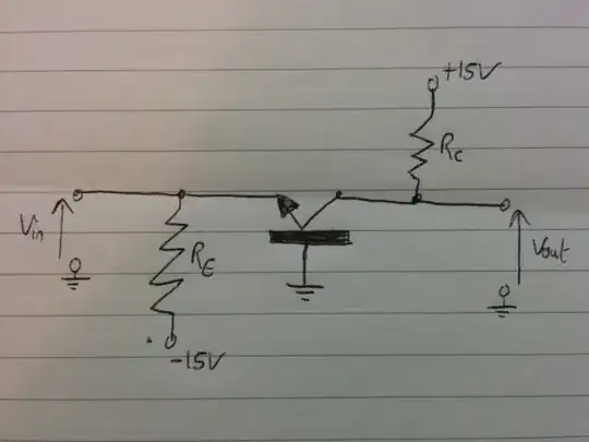
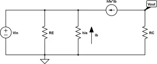
To do this, I drew the equivalent T-model circuit: enter image description here.

The problem I have is that I get two different transfer functions for \$\frac{v_{out}}{v_{in}}\$ depending on which method I use. I originally tried using KCL at the \$v_{in}\$ node: $$\frac{v_{in}}{h_{ie}} + \frac{v_{in}}{R_{e}} = h_{fe}i_{b} = -\frac{v_{out}}{R_{c}}$$ $$\therefore \frac{v_{out}}{v_{in}} = -R_{c}(\frac{1}{h_{ie}} + \frac{1}{R_{e}})$$ The alternative method, which gives the correct solution, is by saying that $$i_{b}=-\frac{v_{in}}{h_{ie}}$$ and that $$v_{out} = -h_{fe}i_{b}R_{c}$$ and thus $$\frac{v_{out}}{v_{in}} = \frac{h_{fe}R_{c}}{h_{ie}} = g_{m}R_{c}$$ as expected.

Why doesn't KCL give the correct answer in this case? I suspect it is something to do with the current source, but I don't know exactly what and it's been baffling me for ages :/.

Dmitry Grigoryev
  • 25,576
  • 5
  • 45
  • 106

3 Answers3

2

Considering just the equivalent circuit, let vin be negative(less than the ground's potential), then current through hie, Re and the controlled source, all flow "into" the vin node, which is not possible, and if vin is positive then all three currents flow out of the vin node, which, again, is not possible. so the only possibility left is vin=vout=0.

You are not really changing any of the signal being supplied to the circuit, in other words, there's no input signal at all, so vin = 0, and it doesn't matter what the gain is, output's gonna be zero as well,

to solve this circuit you need to consider the early effect and add a resistor parallel to the current source, that'll help balance the currents at the vin node,

Salman Azmat
  • 402
  • 1
  • 6
  • 14
2

Why doesn't KCL give the correct answer in this case?

Your equivalent circuit is incomplete since \$v_{in}\$ is, in fact, a voltage source.

schematic

simulate this circuit – Schematic created using CircuitLab

The 2nd solution you provide follows from the above while the 1st solution does not.

Remember, the input must be driven for there to be an output.

When you set out to find \$\frac{v_{out}}{v_{in}}\$, you're asking the question "what is the output voltage \$v_{out}\$ for a given input voltage \$v_{in}\$

By leaving the input open, the only possible value for \$v_{in}\$ is zero.

Thus, if you want to find \$v_{out}\$ for a non-zero \$v_{in}\$, you must apply a non-zero voltage to that node.

Alfred Centauri
  • 26,502
  • 1
  • 25
  • 63
1

I believe you might have made a mistake using the T-model. Notice how Vin is between the two resistors but definitely not connected to the same node as the current source. Hope this helps.

schematic

simulate this circuit – Schematic created using CircuitLab

user43606
  • 33
  • 4