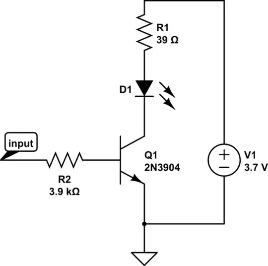
A few basic calculations:
The current through Rled, assuming the transistor is fully saturated:
$$
I_R = \frac{3.7V - 2.4V - 0.3V}{39 \Omega} = 25.6 mA
$$
Looking at a 2N3904 Datasheet, they define saturation as the point hfe=10.
Thus:
$$
I_b = 2.56 mA
$$
This means your micro controller needs a control signal of:
$$
V_m = 0.65V + I_b \cdot 3.9 k\Omega = 10.65V
$$
You didn't specify what your microcontroller voltage supply is, but I'm willing to bet it's 5V or lower. To fix this, either lower the value of Rb or increase the value of Rled.
Assume \$V_m = 3.7V\$ and you don't want to change Rled:
$$
R_b = \frac{V_m - 0.65V}{I_b} = 1189.5 \Omega
$$
So pick \$R_b < 1.19 k\Omega\$ to saturate the transistor.
One other worrying issue:
Having the 2 LED's in parallel as you have implies that the LED's have a very well matched voltage drop. This is usually not the case! In practice you'll get an asymmetric current flow, where one LED could have a significantly higher current than the other. You really should have separate diode current limit resistors if you intend to wire D1 and D2 in parallel.
simulate this circuit – Schematic created using CircuitLab