1

I have a square wave signal whose rise and fall times are too big to feed into another 74xx-series logic chip, such as the 74HC175 flip-flop, which requires rise and fall times in the nanosecond range.

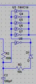
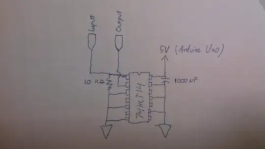
I've tried feeding the square wave signal through a 74HCT14 schmitt trigger inverter, like this: enter image description here

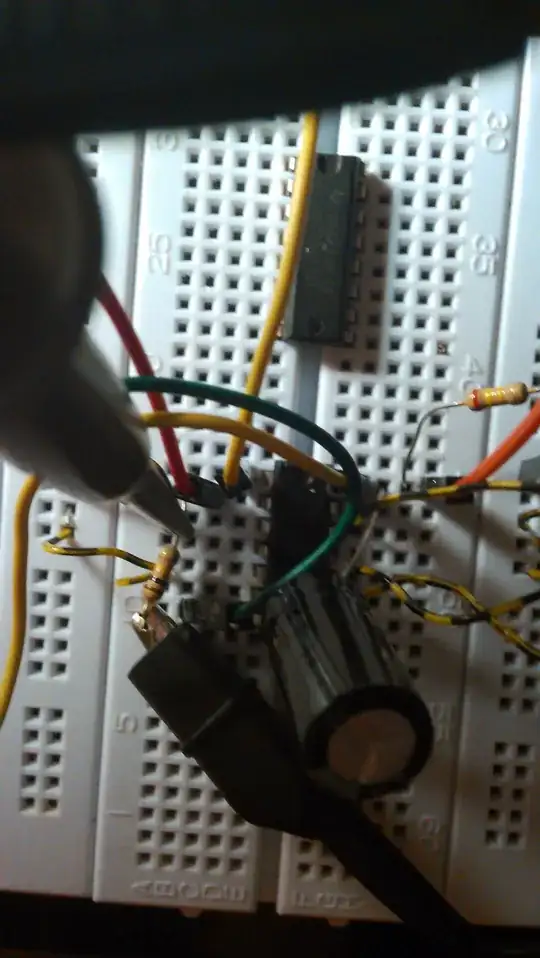
I've built the circuit on a bread board with components that were just lying around - so it's a bit messy: enter image description here

Now, rise and fall times doesn't seem to improve when i feed the signal through the schmitt trigger (yellow: input, blue: output): Yellow graph is input signal - blue graph is output signal enter image description here enter image description here

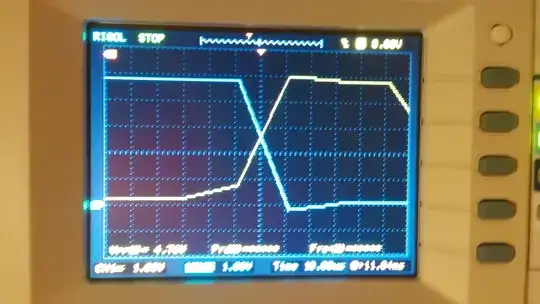
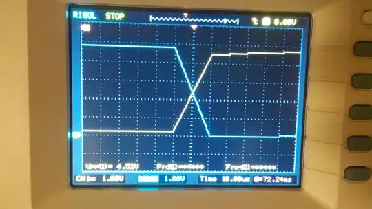
As can be seen, rise and fall times are roughly the same. Also, I find it a bit strange that in the two last pictures the output signal begins transitioning before the input signal has passed Vt+.

The data sheet can be found here: http://www.ti.com/lit/ds/symlink/sn74hc14.pdf

Troels Folke
  • 211
  • 1
  • 7
  • 1
    Add 0.1uF ceramic capacitor as close as possible to the IC. Solderless breadboard prototypes suffer high inductance. For any fast switching part, anything more than about 5-10mm away "doesn't exist" as far as high frequency current is concerned. – MarkU May 27 '14 at 01:49
  • Why do you have a pulldown on the input? – Ignacio Vazquez-Abrams May 27 '14 at 01:49
  • Also, 1000uF is not a decoupling capacitor. – Ignacio Vazquez-Abrams May 27 '14 at 01:52
  • Sorry, I forgot to mention: the input signal is connected to Vcc by a mechanical switch periodically. When it is not connected to Vcc, it must be 0V, hence the pull-down. – Troels Folke May 27 '14 at 01:56
  • What is wrong with using a 1000uF capacitor as decoupling? I know big electrolytic caps have more stray inductance compared to ceramic ones, but I don't seem to have a lot of high-frequency noise on Vcc - especially not after connecting all the other inverter inputs to GND. – Troels Folke May 27 '14 at 02:02
  • So... what you're really asking about is how to debounce a mechanical switch? You don't have enough circuitry there to do an effective job. – Ignacio Vazquez-Abrams May 27 '14 at 02:03
  • No - it seems the switch is already debounced, since there isn't a lot of noise on the input. Just big rise time which I wan't to improve but have trouble with doing. – Troels Folke May 27 '14 at 02:06
  • Supply current will peak whenever the IC's internal transistors switch. The radial leaded 1000uF Al-Electrolytic cap has a low self-resonant frequency (SRF), so it can't help with the peak current demand: there's too much self-inductance inherent to the construction of that type of capacitor. You always need a 0.1uF ceramic capacitor close to each IC, to provide the peak current so the device can operate correctly. Ceramic caps have higher SRF, so they behave like capacitors over a higher range of frequenies, and can supply more peak current to a local IC. – MarkU May 27 '14 at 02:16
  • @MarkU Ok, I will add the 0.1 uF ceramic cap. I don't think I have a noise problem though. How much noise on Vcc (in terms of frequency and peak-to-peak voltage) would you say is too much for an IC like this? – Troels Folke May 27 '14 at 02:30
  • It's not about noise, but rather the peak transient supply current when the output switches. I don't see a power supply in the photo, so there must be some long wires (inductance) which impede the changing flow of current. The local bypass capacitor supplies the high-frequency transient switching current. See also this question http://electronics.stackexchange.com/questions/59325/whats-the-use-of-a-decoupling-capacitor-near-a-reservoir-capacitor – MarkU May 27 '14 at 02:58
  • Nanoseconds and bread-boards doth not good companions make. || As Mark? says - 0.1 uF ceramic cap near Vcc and gnd, short leads. As deleted Tony says - scope connections matter. Keep earth probe short and connect near relevant earth point. || Scope MUST be in direct sampling mode. If you are getting multiple sweeps per image results are mush. – Russell McMahon May 27 '14 at 12:42

2 Answers2

4

It looks like you've got the oscilloscope displaying some uber-expanded portion of a capture- it's only changing slope every two horizontal divisions .. so anything faster than that all looks the same.

The first photo shows it changing slope every division, rather than two divisions in the bottom two photos, but in each case it's 20\$\mu s\$ per division, which implies your effective sample rate is only 50ksps, as @RJR comments.

If you want to see 74HC rise and fall times, 1Gsps would be more appropriate.

Spehro Pefhany
  • 376,485
  • 21
  • 320
  • 842
  • Good point. It seems it only samples once every division - 20us which translates to 50KHz??? – RJR May 27 '14 at 03:01
  • Thanks, I was not aware of my scope's sampling rate. – Troels Folke May 28 '14 at 13:56
  • Your scope isn't 50KHz, it is 50MHz and should work fine for viewing this. Are you using triggering, or are you manually stopping it and zooming in? Zooming in doesn't work, you don't get as much resolution. Setup a trigger. – THEMuffinMan7 May 30 '14 at 05:37
0

I've used the same chip before with no issue. It definitely transitioned in the ns range, maybe about 10ns or less. Mine was wired up like this, but was sort of used as a pulse generator with the cap charging/discharging. The input goes into U8 there and the output is inverting like yours. Hope this helps.

Pretty sure we have the same scope

enter image description here

Edit: Use triggering on you're scope if your not! Don't just stop the waveform and zoom in - it doesn't work! I did that, took me days to figure it out.

THEMuffinMan7
  • 357
  • 4
  • 13