I found this in CRT TV on the CRT tube driver PCB.
What are they and what is their schematic symbol?
I found this in CRT TV on the CRT tube driver PCB.
What are they and what is their schematic symbol?
As noted in comments, the part shown in the photograph is a spark gap. This page lists several such spark gaps and similar / related parts.
Below is an inert-gas filled spark gap, closest in functionality to the part in the question, yet safer due to being glass encapsulated:
A more common modern version of this device is offered by Littelfuse and others, and comes in several different packages:
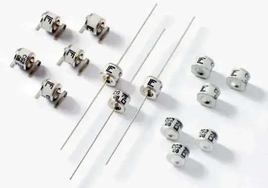
The through-hole versions are available on eBay for around $1 to $2 in single units, if you would like to experiment with one.
Various schematic symbols for spark gaps are documented on WikiMedia:
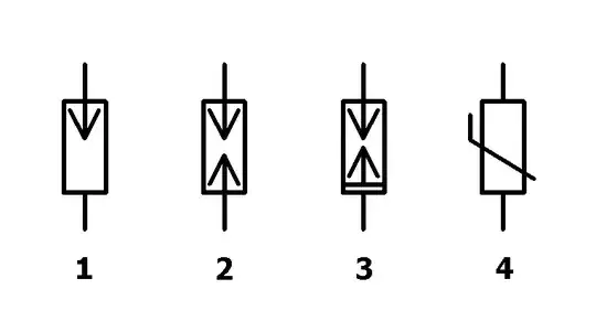
Of these, symbol #2 is most commonly supported in the schematic software I have used.