6

I'm trying to understand this mechanical drawing. (Another one. I asked a question about mechanical drawings a while back.)

enter image description here

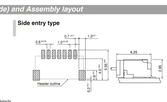
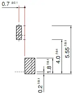
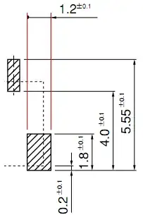
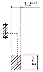
I can work out most of the dimensions, but the mount pads are confusing me. They have two numbers (0.7 and 1.2) beside them. They could be any size for what I know...!

The drawing is for an SH type connector.

Many thanks.

stevenvh
  • 145,145
  • 21
  • 455
  • 667
Thomas O
  • 31,546
  • 57
  • 182
  • 320

2 Answers2

13

The 0.7 is the distance from the center of the smaller (contact) pads to the edge of the larger (mechanical) pad.

enter image description here

The 1.2 is the width of the larger pad.

enter image description here

Notice the dot both arrows point to.

edit
You'll often see the indication BSC next to one of the measurements. This means Basic Spacing between Centers and is a nominal value. Could have been given here next to the 1mm (pitch) value, or next to a 6mm value between centers of first and last pad.

stevenvh
  • 145,145
  • 21
  • 455
  • 667
  • 1
    I put some images to help clarify better. – Daniel Grillo Mar 04 '11 at 12:27
  • The answer above "answers" the question to a point... For me, if it's important enough to dimension to the header outline on Y why not tie it down by giving X dimension to the edge of the header outline? –  Aug 26 '12 at 01:58
  • @taf: Welcome! This site is not a forum, and posts are not ordered chronologically. Answers are supposed to address the question, and if you want to comment on a post there is a specific tool. I took the liberty to convert your post into a comment, I hope I guessed right about the referred post. – clabacchio Aug 26 '12 at 14:57
6

They are actually 1.2 x 1.8.

enter image description here

The dimensioning could be a lot clearer.

I wish that they would dimension to the pad centres That is how most PCB packages work.

Leon Heller
  • 38,774
  • 2
  • 60
  • 96