16

enter image description here

We start from the Maxwell's Equation

$$ \mathbf{\nabla} \times \mathbf{B} = \mu \mathbf{J} + \overbrace{\mu \epsilon \dfrac{\partial \mathbf{E}}{\partial t}}^0. $$

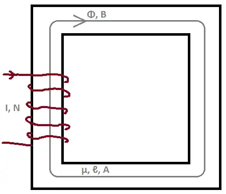
We take surface integration of both sides, for the surface (\$s\$) inside the mean path (\$c\$) of the core.

$$ \int_s \left( \mathbf{\nabla} \times \mathbf{B} \right) \cdot d\mathbf{s} = \mu \int_s \mathbf{J} \cdot d\mathbf{s} $$

We use the Stroke's Theorem to rewrite the left hand side; where \$c\$ is in the same direction with the magnetic flux \$\Phi\$.

$$ \oint_c \mathbf{B} \cdot d \mathbf{\ell} = \mu N I $$

(The integral on the left hand side results \$NI\$, because there are \$N\$ different wires on the winding.)

The magnetic field density inside these kind of cores are considered to be uniform. So, we can write

$$ B \ell_c \overset\sim= \mu NI \implies B = \dfrac{\mu NI}{\ell_c}; $$

where \$\ell_c\$ is the mean path lenght of the core.

We can find magnetic flux from the magnetic flux density we have found by using the cross sectional area of the core \$A_c\$.

$$ \Phi = BA_c = \dfrac{\mu NIA_c}{\ell_c} $$

By definition, inductance is the amount of magnetic flux generated per applied current, that is

$$ L \overset\triangle= \dfrac{\Phi}{I}. $$

So, we find inductance of the system as

$$ \boxed{ L = \dfrac{\Phi}{I} = \dfrac{\dfrac{\mu NIA_c}{\ell_c}}{I} = \dfrac{\mu NA_c}{\ell_c} }. $$

But, all other sources (example) give inductance of an inductor like this as

$$ L = \dfrac{\mu N^2A_c}{\ell_c}. $$

What is the mistake I did in my derivation? Please explain in detail.

Dan D.
  • 672
  • 7
  • 11
hkBattousai
  • 13,913
  • 31
  • 114
  • 190

3 Answers3

12

Think of a single turn inductor (left below) then, imagine that single turn split into two parallel wires that are wound very tightly so that they occupy virtually the same space (right below).

The two parallel wires, for a given applied voltage, will each take half the current of the single turn inductor and, together they take the same current as the single turn: -

enter image description here

Because of this, each individual parallel wire MUST have twice the impedance of the single wire and, together, when wired in parallel, exhibit the same impedance as the single wire. OK so far?

Now, re-arrange those two wires (in your mind's eye) so that they are in series with each other. The impedance changes to four times the impedance: -

enter image description here

This means the inductance has quadrupled for a doubling of turns and it is trivial to extend this example to n turns.

Andy aka
  • 434,556
  • 28
  • 351
  • 777
11

You calculate the core flux with the equotion above, and the inductance takes the sum of all fluxes through each turn. The flux through each turn is the same and equal to core flux. The core flux is proportional to N, and the per-turn sum of flux is proportional to \$N^2\$.

Another way to express this dependancy is to say: because of magnetic coupling between turns.

motoprogger
  • 1,301
  • 9
  • 10
  • Do you mean that, N turns contribute for generating the flux, and once again these N turns contribute in a different way for creating the induction, so that the inductance becomes proportional with N for twice; that is N²? – hkBattousai May 10 '14 at 13:30
  • 6
    Yes, they contribute for the first time generating the core flux and the second time "gathering" it. – motoprogger May 10 '14 at 13:34
6

What is the mistake I did in my derivation? Please explain in detail.

The inductance is

$$L = \frac{\lambda}{I} = \frac{N\Phi}{I} $$

where \$\lambda\$ is the flux linkage - the magnetic flux links N turns.

Alfred Centauri
  • 26,502
  • 1
  • 25
  • 63