9

Or perhaps, what are the best bands/modulations to choose from if I need to efficiently transmit data in a path with heavy metal obstacles?

I need to build a number of devices to periodically transmit short bursts of data in a large storage facility full of metal containers (which are either empty or full of unknown contents). I've been performing tests with ZigBee transceivers (e.g. Atmel's ZigBit line) with various degrees of success. I've had very poor results in the 2.4 GHz bands and very acceptable results in the 900 MHz bands. However, I've been told by some people I've met that they've had the exact opposite experience (in their case, they were using 2.4GHz/900MHz XBee modules). I'm aware that 433 MHz is also a common band, and there's of course 5.8 GHz too.

So, the main part of the question is if there's some kind of chart or common knowledge about what frequencies are particularly good or bad for this kind of transmission. I'm interested in the bands I can use in small devices (e.g. phone sized) with battery power. A range of 50~100 meters/yards with obstacles would be very nice. Also, there should be some kind of chipset or module commercially available to deal with the RF part of the device (i.e., modulation, RF front end, clear-channel detection, preamble detection, etc.); I can deal with the higher level protocols myself.

Ideally, it would be a band for which I can use some kind of antenna that would not detune too easily if placed very close to a large metal object (1 inch/2.5 cm. from it). I've been testing mostly with whip and helical antennas. My devices must be placed very close to the metal surfaces it needs to overcome!

I cannot, however, count on: antenna directionality, device location/orientation, fixed transceiver locations, etc. All devices will be placed very randomly and scarcely. I just need to make the best I can. Only one thing I can count on is that the devices will stand always in vertical position.

JYelton
  • 32,302
  • 33
  • 134
  • 249
Guillermo Prandi
  • 897
  • 1
  • 10
  • 24
  • Step back and try and describe functionally what you are trying to achieve without mentioning radio or transmission types. – Andy aka May 09 '14 at 11:08
  • @Andy, thank you for your interest. Further application information is irrelevant since I cannot change anything about it. What I need is advise about radio and transmission types. – Guillermo Prandi May 09 '14 at 15:02
  • 1
    I'm asking you to describe functionally what you need - I'm not asking you to forget about radio. – Andy aka May 09 '14 at 15:06
  • I need to establish kind of a "mesh" network between nodes with sensors installed magnetically on the doors of metal containers. Each sensor is battery powered and must transmit data to a base antenna (which incidentally must have the same electronics as the nodes and is placed on one corner of the premises). Data is transmitted every 4 minutes and node count can go from a few to a couple thousands. There's a protocol (already tested in software simulations) that can handle that many nodes, provided data packet tx time is below certain limits; node visibility is the key. Does that help? – Guillermo Prandi May 10 '14 at 00:32
  • Is the plan for the door sensors to be "transmit only" ie just blind transmitters and yes, your description of functionality helps loads. If transmit-only then I can say I have done a similar system and to make it work in less-than ideal RF conditions I used multiple receivers strategically placed all on phantom powered RS485 feeding a data collection unit. Think of it like a cellular system where initially the best receiver for a given transmitter was established by a set up process then after that each receiver was instructed to forward only the data from certain transmitters. – Andy aka May 10 '14 at 10:03
  • The protocol needs every device to be a retransmitter. I cannot place anything "ground installed" (as a RS485 or Ethernet installation). Every device, even the base, is battery powered and removable upon request. Imagine the cargo bay of a ship. Devices are installed when the trip begins and removed when the ship arrives. – Guillermo Prandi May 10 '14 at 12:27

2 Answers2

9

The rule of thumb a lot of people use is that lower frequencies will have better "penetration" than higher frequencies. That's true in some cases, but not all. This is probably derived from calculating skin depth of materials. The skin depth is just how deeply into a material an electromagnetic wave of a particular frequency can penetrate. The equation used when the material is a good conductor is:

$$ \delta = \sqrt{\frac{2\rho}{\omega\mu}}\ $$

where ρ is the resistivity and μ is the permeability of the material. What you should notice though, is that as frequency (\$\omega\$) gets bigger, the skin depth gets shallower. Here's a practical example of what that means: your microwave shoots out radio waves at 2.4 GHz. If you put a giant thick steak in there, and we measure it's resistivity and permeability, we can calculate the maximum thickness of steak you can cook in your microwave. Anything deeper than the skin depth won't get cooked, because all of the energy of the microwave will have been absorbed already.

There are charts like you mentioned about how well different materials absorb radio waves, but they're not linear or predictable, so there isn't really a rule of thumb that's easy to apply. Here's how well every element in the period table absorbs photons (electromagnetic radiation). The energy on the Y axis is proportional to the frequency:

enter image description here

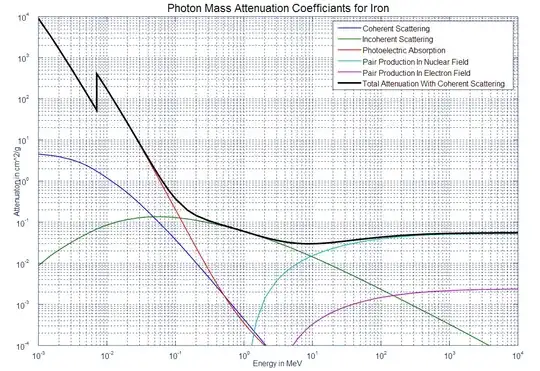
But this chart of Iron's absorption (according to different mechanisms) shows how things get messier when you zoom in:

http://forums.solidsignal.com/content.php/190-What-is-multipath-and-what-can-I-do-about-it

But in your application, there's another factor at play, which probably has a bigger effect. When your transmitter starts going in your big facility, it sends off an electromagnetic wave in all directions (assuming you're not using a directional antenna). Those waves will travel through the air until they encounter another medium, like the metal in the containers. When the wave hits that container, some of the energy is absorbed into the container, and some is reflected off the container. The part that's reflected will travel until it hits something else and then some will be absorbed and some will get reflected again. This is called multipath. Your receiving antenna might get a bunch of copies of the originally transmitted signal, all slightly time delayed. Here's an example of what it looks like when an analog TV is suffering from multipath problems:

enter image description here

Because multipath effects can cause waves to destructively interfere with each other, that's probably why you're getting conflicting results. The position of the antenna and transmitter and containers will change the performance a lot, and if things are moving around in the facility, you may get a great signal one moment and then all of a sudden it will be terrible.

Dealing with multipath is hard, but here are a couple things you can try. Make the receive antenna directional, so it will hopefully have a low sensitivity to reflected signals. If you can get the antennas high up above the containers, that may help too. I would experiment with a 433 MHz transmitter (there are a bunch of companies that make modules) because I think you'll get better performance versus 2.4 GHz or 5.8 GHz.

chwi
  • 1,241
  • 2
  • 11
  • 21
aloishis89
  • 1,660
  • 3
  • 13
  • 20
  • Thank you for your answer! Indeed it's a nightmare scenario for RF transmission. The antenna is not very directional since I can't predict the position of each sensor. It's a classic 1/4 wave whip dipole, so it's "more horizontal than vertical", which is good for me. I agree with you about the multipath being a big problem. Antenna tunning is a problem too; I'm no antenna expert so it's difficult for me to predict how the environment (or even the device case!) will affect it. Any hints for that? – Guillermo Prandi May 09 '14 at 14:56
  • Well, if it's sitting on top of a grounded metal surface, that's good for performance. Obviously don't put the antenna inside a metal case. To make sure all the energy is being radiated, you can use an SWR meter. – aloishis89 May 09 '14 at 15:42
  • It's not on top of the metal surface: it's beside! The metal containers are 2.5 meters tall and the device is places at mid-height. Sorry I didn't clarify that. – Guillermo Prandi May 09 '14 at 16:24
  • That will give you problems since the container walls parallel to the antenna will themselves start to radiate (image effect) and cancel the waves from the antenna. The antenna will also couple to the metal walls and it's impedance will change, so you'll get a bigger VSWR (which is bad). So try using a vertically polarized antenna (relative to the metal walls) and use an SWR meter to make sure the antenna is matched (ie all the energy from the transmitter is getting radiated through the antenna, not reflected back into the transmitter circuitry). – aloishis89 May 09 '14 at 16:50
  • Vertical "relative to the metal walls" would be perpendicular or parallel to them? (the device is installed on the wall, near its center). I've been doing tests with whips placed vertically (as in standing from the floor, parallel to the containers' walls). I've also tried with helical antennas, also in vertical position. By the way, how can I determine the polarization of this kind of antenna? http://www.digikey.com/product-detail/en/W3012/553-1676-1-ND/2543337 – Guillermo Prandi May 10 '14 at 00:53
  • Parallel. If you've been trying stuff vertically, then maybe you're already getting all you're gonna get from that. I'm not sure what the polarization of a chip antenna is. I think the idea is that even though the chip antenna is smaller than the wavelength, they load it with inductance to make it look electrically bigger (although it adds loss). So it should act like a tiny dipole and have linear polarization. – aloishis89 May 15 '14 at 18:45
1

Higher frequencies tend to refract more and respond more dramatically to sharp angles, as in knife edge propagation. This can be good sometimes, as it allows your signal to reach places it couldn't otherwise reach. You may need to modify your antenna once it is mounted, since the metal containers will affect the resonance of the antenna, but by modifying them to lower the swr after they are in place, you can counteract a lot of that. You don't want the emitted frequency to be too high or too low, or it will not respond well in a high metal environment. Somewhere in the area of 150-1000 MHz would probably work well.
To find the polarity of that antenna, you could connect it to a transmitter and listen to the transmitted signal on another radio at some distance. Try tilting the antenna on the receiving radio back and forth between vertically aligned and horizontally aligned. When the signal is strongest, that is the transmitting antenna's polarization. There can be up to a 90% drop in signal strength when the polarity of the two antennas are different.

Delta1X
  • 75
  • 8