1

Background

I wanted to make a simple function generator with an ATmega328 and an R2R resistor network, similar to Jesper Hansen's Mini DDS (Direct Digital Synthesis).

To make the function generation firmware run fast enough, I believe I have to wire an entire PORT (all of its 8 output pins) on the ATmega328 to the R2R resistor network. This way I can write one full byte to the port with a single command, like so:

PORTD = B10101000;

On the ATmega328, I think PORT D is the only port I can use like that. ATmega328 pinout and port distribution is below.

ATmega328 pinout

The Problem

The problem I'm facing is that I also want to use the ATmega328 serial port for programming the board, but the serial port is also on PORT D (pins PD0 and PD1), thus creating a conflict.

Proposed Solution

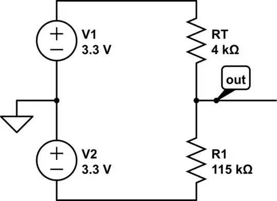
After some research, I've decided that I could get away with the design below. The relevant part is circled in green.

My schematics combining UART and R2R network

With that circuit I think I'll be able to use the serial pins for programming the board and also, but not at the same time, drive the R2R network to produce a sine wave.

Considerations

The considerations I gathered so far, including contributions from comments, are the following:

  1. R17 is required to protect whatever is connected to the RX line (e.g. MAX232 IC) when ATmega pin 2 is changed to an output to drive the R2R network. That will prevent a large current from being sourced by the MAX232 IC when the pin is driven low.

  2. R17 value (1kΩ) will slow down RX line a bit (increase rise and fall times), but according to what I understood from this answer by Leon Heller - Resistors in series with Tx and Rx, it won't be enough to prevent serial communication (pending experiments to prove it).

  3. I won't be able to use both functions at the same time, but that's ok, as I plan to switch between functions in the firmware.

  4. RX and TX lines are linked to each other by a 50kΩ equivalent resistance, by R1, R2 and R3. That will create a 0.1mA current in and out of each pin, when they show different logic levels. I think that won't be a problem, but further experiments are required.

Questions

My questions are:

  1. Will my circuit work? If not, why not?
  2. Will this circuit burn or stress my ATmega or whatever I connect to the serial connector?
  3. Is there a better way to do it using an ATmega328 and the R2R network?

I know there are a lot of ADC chips out there that would help me solve this problem easily and would make my miniDDS more precise, but I wanted to start out with these requirements.

Ricardo
  • 6,134
  • 19
  • 52
  • 85
  • 1
    Moving up to a ATmegaXX4(A/P) will give you 4 8-bit buses, so you can use (almost) any at your leisure. – Ignacio Vazquez-Abrams May 06 '14 at 00:02
  • 1
    Were you planning to just plug in the MAX232 or similar just for programming? About the only problem I can spot is that RX line being high or low to would interfere with your output to some degree. – PeterJ May 06 '14 at 00:29
  • @PeterJ - Yes, I'm planning on using this miniDDS with [my MAX232 based TTL-to-RS232 converter board](http://electronics.stackexchange.com/questions/104466/problems-with-homemade-rs232-to-ttl-converter-board-based-on-tis-max232) which finally decided to work. But I know I won't be able to use the serial comm with the R2R output at the same time. I plan on switching between them in the firmware. Maybe I should have made this clearer on the question. In any case, I've edited the question accordingly. – Ricardo May 06 '14 at 00:31
  • And if you can live with slimming down, there's the ATtiny2313A/4313. – Ignacio Vazquez-Abrams May 06 '14 at 00:44
  • @Ignacio - Yes! Jansen's miniDDS is based on the 2313. It has a full PORT D for the R2R network separated from the serial pins. But I'm just a hobbyist, and I don't have the tools, time, money, skills and open mind to keep on expanding my MCU base. – Ricardo May 06 '14 at 01:04
  • But ISP is *awesome*. (And Atmel has a sample program.) – Ignacio Vazquez-Abrams May 06 '14 at 01:29
  • 1
    You are going to run into a problem with the configuration in your 2nd picture. Your RX and TX line are tied together through 50Kohm resistance. On top of that, your signals are going to have longer rise and fall times because of these resistors so the device you'll be talking to might not understand the atmega328 – Funkyguy May 06 '14 at 14:08
  • @ShannonStrutz - Well spotted! I missed the 50Kohm link bewteen RX and TX, completely. Do you think that will make a difference given that the resistance is relatively high? – Ricardo May 06 '14 at 14:12
  • 1
    I couldn't really say, I want to say you'll be safe but I literally have no justification as to why. If you have to do it that way, then you'll have to do some experimentation. I don't know if this will damage your controller though. – Funkyguy May 06 '14 at 20:57
  • 1
    why cant you have just a nice big two-circuit switch, which changes the rout from TX/RX to serial header, or to the R2R Ladder? – KyranF May 07 '14 at 23:59
  • @KyranF - I'd love that! You mean a mechanical or a transistor based switch? Can you elaborate a bit on that? – Ricardo May 08 '14 at 00:21
  • 1
    If I wanted to be absolutely sure that my JTAG/ICSP/[insert programmer here] functionality didn't affect the far side I/O, I would insert a tristate buffer like the trusty 74LS125 that puts the the R2R network at high impedance, effectively disconnecting it while programming. – BB ON May 08 '14 at 00:33
  • Something like this mate, http://www.jameco.com/1/1/27618-35-222-bu-dpdt-slide-switch.html . This will allow you to have two lines (RX and TX from UART) switched physically/mechanically between the R2R ladder inputs, or the outside world via serial port. – KyranF May 08 '14 at 10:23
  • Exactly the same system is used to switch between two different TX/RX connections (in your case, a TX RX and a two R2R connections) on the Arduino Xbee Shield, for swapping between programming the Arduino via serial and Xbee->Arduino Serial comms. They use a double pole double throw PCB mount switch. It works man! – KyranF May 08 '14 at 10:28
  • You can also do two three-pin jumpers nearby eachother, and have the middle line as the microcontroller's RX and TX pins, and you use those little two-pin jumpers to connect RX to either an R2R connection, or to Serial RX, and similar for TX. – KyranF May 08 '14 at 10:35
  • @KyranF: I see what you mean. I thought of having a mechanical switch but got discouraged by the fact that I can damage the comm device if the switch is in the wrong position. If I were to have a switch, I'd rather have a transistor based one to avoid that. Even then, the solution would not be optimal, as a bug in the firmware could damage the comm device all the same. Since this will be a one-off board made for hacking, that's very likely to happen. – Ricardo May 08 '14 at 11:10
  • How much space have you got for circuitry? You can do some sneaky timed latching and un-latching based off reset during programming. Like, upon detection of the reset pulse from DTR on serial, you can use a 555 timer to disable the connection between R2R and the serial lines (with a PNP transistor or something, you get the idea) and perhaps only when the microcontroller starts back up again, you use a Digital IO pin to un-latch/return operation to normal. to make the board safe again, perhaps have a button which pulls reset low too, which will latch the off state as mentioned until micro says! – KyranF May 08 '14 at 11:26
  • I said timed, but really you just want a flip-flop / D latch circuit which is normally in a 'safe' connection to RX-TX. You can also use as someone said a tri-state buffer/line driver with enable pin from the microcontroller to activate the R2R style connection (will be a crazy signal if serial was also attached at the same time though lol) either way you will not 'damage' anything – KyranF May 08 '14 at 11:29
  • Wow, Ricardo I think i found the answer! Check Andy Aka's answer to this question, http://electronics.stackexchange.com/questions/109588/mosfet-for-h-bridge . it's a dual SPDT switch which means it's basically DPDT as we need for your application, and you can rig up some latching/reset pulsed circuitry do the switching! – KyranF May 08 '14 at 12:53

1 Answers1

1

I have answers for all your stated questions:

  • Your circuit will not provide a varying voltage on the output by itself, just a varying current source. The actual voltage generated will depend highly on the impedance of the device connected to the output. You may want to fix this with an additional resistor to ground, and/or an opamp.
  • Your circuit will likely allow serial communication, especially at slower rates like 19200 which I think are by default used by Arduino-style serial bootloaders. The 50 kOhm pull-up effect doesn't matter. The 1 kOhm resistance doesn't slow down too much.
  • Your circuit is unlikely to burn or stress the Atmega or the serially connected device.
  • I can think of three other ways, see below.

The first way would be to use a ICSP USB programmer to program the Atmega instead of serial programming, Arduino-style. This is more robust, faster, and avoids the problem entirely, and optimizes for BOM cost for the actual device (at the expense of requiring a few dollars of programmer hardware if you need to actually program it.) This can be implemented even on an Arduino board.

The second way is to run the Atmega328p on the internal RC oscillator, not using a crystal, and use port B instead of port D for the DDS output. This leaves the serial port entirely un-touched.

The third way is to write PORTB and PORTD one after the other, and use PORTB for the two bits that the serial port uses. This will generate a two-cycle glitch at about 4-8 Mhz. Given that you will need a low-pass filter anyway to generate any kind of smooth waveform, you simply need to lower the cut-off frequency of that filter to eliminate these glitches. To properly write the two ports in sequence, load the values into registers, disable interrupts, write the two ports, and re-enable interrupts.

Finally, you could use a small-signal diode (like 1N4148) instead of R17.

Jon Watte
  • 5,650
  • 26
  • 36
  • Thanks for the detailed answer. That's what I was looking for. One question though: I need the serial communication to work at 76800 and 115200. Will my circuit work at those speeds? – Ricardo May 08 '14 at 18:34
  • Also, can you tell me how to place the 1N4148 on the RX line? Does the anode goes into the ATmega RX pin? – Ricardo May 08 '14 at 18:41
  • 1
    The circuit will likely work at 115200 bps. Compare to I2C at 1400 kHz, where a 2 kOhm pull-up provides sufficient current. Separately, if the idea is to let the RX pin pull up the output network, but not let the output network affect the RX pin, then anode to RX, cathode to network, would be the right direction. Beware the voltage drop of the diode, though -- this may or may not be a problem for you. – Jon Watte May 09 '14 at 20:25
  • Thank you so much for taking the time to answer my question. That was exactly the kind of response I wanted! The bounty is yours. Congratulations!! – Ricardo May 10 '14 at 22:17