When all you have is transistors, it handy to be able to fall back on RTL design techniques.
First of all, you're going to want to be able to latch the first button pressed, since contestants will often just press the button momentarily. Then, when things settle down, the moderator or quiz master can reset the circuit for the next question.
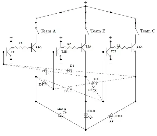
Here's my proposed circuit:

simulate this circuit – Schematic created using CircuitLab
Consider the circuit for just "contestant A". Q1 is a 2-input NOR gate, and Q2 is a 4-input NOR gate. Together, they form a set-reset flip-flop, via the feedback paths through R4 and R6. There is one other "set" input through R3 (from the button) and three other "reset" inputs: one from the master reset and one from each of the other circuits. It's important to note that any of the reset inputs take priority over the set input. The first contestant to hit his button will set his flip-flop and inhibit all of the others.
Additional Refinements
The basic circuit can be enhanced in a couple of ways.
For one thing, the inputs are contact closures to the power supply. There are a number of reasons you might prefer them to be contact closures to ground, particularly if you'd like to put the buttons into pendants that the contestants hold (possibly using a plug and jack arrangement so that they can be detached). You can add a simple inverter to each input:
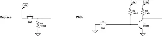
simulate this circuit
For another thing, you might want to have more flexibility in the type of indicators you use. (The basic circuit relies on the fact that the forward voltage drop of the LEDs is sufficient to act as a logical '1' in the feedback path.) In order to drive brighter LEDs, or a string of LEDs, or some other type of indicator, you could add output buffers. This would permit the displays to be driven from a different voltage than the one that powers the logic.
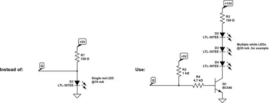
simulate this circuit
Adding more buttons and indicators with this circuit can become problematic, because the noise margin of this type of NOR gate degrades with higher fan-in (number of inputs per gate). Using diodes would help mitigate this.
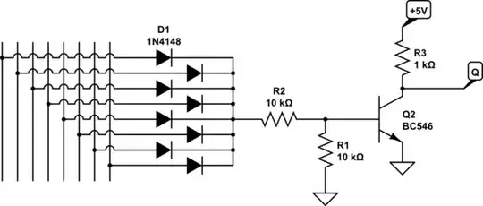
simulate this circuit