2

I have the following tank circuit. Now at resonance of about 50.054 MHz, the output voltage should be same as input, as the tank circuit would have a high resistance.

Tank circuit schematic

I have calculated the impedance of the tank circuit at the resonance frequency to be

\$Z_{total} = \dfrac{j\omega L}{1-{\omega}^2 LC}\$ = 4.5M\$\Omega\$

Then why is the output voltage so much attenuated?

enter image description here

Also as a second question, what would be the output impedance of this circuit?

I found it to be

\$\dfrac{1}{Z_{out}} = \dfrac{1}{R1} + \dfrac{1}{Z_{total}}\$

\$\Rightarrow Z_{out} = \dfrac{1}{\sqrt{(\dfrac{1}{R})^2 + (\dfrac{1}{X_{total}}) ^2}}\$ = 1k\$\Omega\$. Is this correct?

Note: The series resistance of the inductor is zero, and not the default of 10m\$\Omega\$

Ricardo
  • 6,134
  • 19
  • 52
  • 85
Arjob Mukherjee
  • 608
  • 7
  • 17

3 Answers3

3

The transfer function is

$$\frac{V_{out}}{V_{in}} = \frac{j\omega \frac{L}{R}}{(1 - \omega^2LC) + j\omega \frac{L}{R} }$$

The Q is given by

$$Q = R\sqrt{\frac{C}{L}}$$

So the Q is proportional to the series resistance \$R\$ and, for your values, is quite high

$$Q = 1k \sqrt{\frac{244.8p}{41.3n}} \approx 77$$

With this high \$Q\$, the transfer function magnitude rapidly changes near the resonance frequency so simulation round off may greatly affect the results.

I tried \$R=100 \Omega\$ which reduced the \$Q\$ by a factor of 10 and the simulation output is very nearly the input after a number of cycles.


Update:

I adjusted the "step ceiling" parameter for the transient simulation down to \$10^{-12}\$ and I get a good simulation with \$R=1k\Omega\$.

enter image description here

Alfred Centauri
  • 26,502
  • 1
  • 25
  • 63
2

Using an LC parallel tank circuit from any voltage source will get loaded in parallel from the source series resistance. The maximum output signal will only be 0dB attenuation and only at precise resonant frequency with zero phase shift. Since phase shift goes from -90 to +90 over the 3dB bandwidth of the tank circuit, error frequency will produce a non-zero phase shift and attenuate from ideal 0 dB loss. You cannot get any gain from a voltage source.

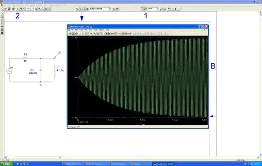
Since your simulation has a phase shift, it will also have attenuation according to the % error x Q. 
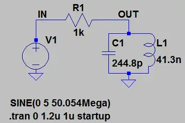
For example of your circuit with cursor offset see attenuation and phase shift.

enter image description hereThe proper use to achieve voltage gain* of an LC parallel resonant high Q circuit is to use a current source ( very high impedance) and similar very high impedance load, such as on a common emitter stage with L between collector to Vcc. Then the Q will be determined solely by the load Resistance /Reactance of either element at resonance and voltage gain determined by high ratio of collector load to emitter resistance.

Start by choosing the load resistance and resonant frequency, then choose L or C according to desired Q then match the other reactive part for resonance.

For practical concerns Q=100 is easily achievable, which means only 2 or 3 significant figures for frequency, and not 5 as in your example. Stray capacitance MUST also be factored and L leakage capacitance or self resonant frequency, as well.

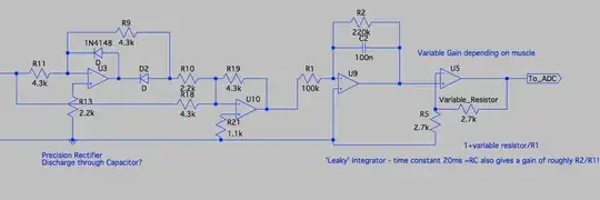
As an aside note, For crystals, and MEMS resonators ~ 10k for Q is normal. But when used in oscillators with say 1k series resistance the amplifier must have at least a gain of 10 to square up the sine input signal. This gain=10 is true in all CMOS gates unless they are buffered, i.e. 3stages or gain=1000. If you put your circuit in a CMOS inverter feedback loop, treat it as a voltage source. If using a BJT, treat it as a current source.

1

First, the output voltage is not much attenuated considering the impedance of each of the resonant components individually, which is about 13 Ω at 50 MHz. With just the capacitor without the inductor, the output would be much more attenuated. You'd barely see it, if at all, on the scale of your plot.

Second, it should be obvious from your scope traces that you are not exactly at resonance. Since the output is lagging the input slightly, the capacitance is dominating the inductance a little bit.

Use a signal generator so that you can vary the frequency. You should find that the largest amplitude output will be a little less than the frequency you are using now. At maximum output, there should also not be any phase shift between input and output. Even then, there will be a little attenuation since the components aren't perfect.

Olin Lathrop
  • 310,974
  • 36
  • 428
  • 915
  • I am using LTSpice, So I expected ideal results. Anyway, what would be the output impedance of this circuit? – Arjob Mukherjee May 01 '14 at 15:51
  • @Arjob: It is still very close to resonance, just a little off. Try a slightly lower frequency. As for the output impedance, that would be 1 kOhm at resonance, of course, because the ideal parallel tank circuit has infinite impedance at resonance. – Olin Lathrop May 01 '14 at 15:56