1

I am currently trying to build an op-amp circuit which allows seperation of send and recieve signals from the UK telephone line (or a simulation of the telephone line).

I am having difficulty understanding how certain values are calculated within the circuit.

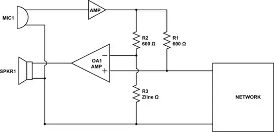
The basic circuit is:

-Unity Gain stage from output from send

-Telephone impedance matching network

-Differential amplifier taking in signal before mixed onto the line and after mixing onto the line.

I need the diff amp output to be on a offset (as I am running it on single rail supplies). The idea is that the output from the diff amp should be just the received signal (i.e. none of the transmit signal).

The major confusion comes from the level of the signals at each stage and how to adjust the component values to match this. I suppose really I don't understand how the line termination works and so therefore how to effectively remove the send signal from the transmit path.

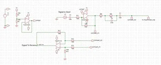
Here is a circuit diagram of what I have currently built (if you right-click and open it in a new tab, it's possible to zoom in to view my component values): Circuit Diagram

Any help would be most appreciated!

Thanks

-- EDIT Following the suggestions I have updated my circuit diagram. However the issue I now get is that the output ADC_IN does not contain any of my received signal (if I place a waveform generator on the other side of the line). I am assuming I have missed something....

Modified_circuit

Matt Taylor
  • 123
  • 12

1 Answers1

1

I suppose really I don't understand how the line termination works and so therefore how to effectively remove the send signal from the transmit path.

Basically, a telephone handset works like this: -

schematic

simulate this circuit – Schematic created using CircuitLab

As can be seen the microphone amplified signal is split into two paths via 2 resistors R1 and R2. If R3 matches the real network line impedance at all relevant frequencies, then amplifier OA1 will only amplify the signal from the network and there will be minimal "sidetone" from microphone to handset earpiece.

Andy aka
  • 434,556
  • 28
  • 351
  • 777
  • Thanks for your answer Andy. I understand that, but the problem that I'm having is getting the diff-amp to operate on a single-rail supply, rather than a dual-rail. Also, would this work with impedances other than 600 Ohm? I'm building it for an EU phone line, which uses a termination of 370ohm + (620ohm||310nF). – Matt Taylor Apr 30 '14 at 15:24
  • Using a different impedance such as the complex one you list is not a problem. Use the impedance to drive to the line to form a 2:1 divider and matched resistors for the cancellation circuit and it'll work. – Andy aka Apr 30 '14 at 16:17
  • Try R15 tied to your mid-rail generator's output (OFFSET). If the network line can be called R4 then you only have to make R1/R4 = R2/R3 (by whatever means within reason). – Andy aka Apr 30 '14 at 16:58
  • Hi Andy, thanks so much for your help so far. As you can see from the original question I have added a modified circuit with the suggestions you made. It works fine when there is only one source generator, however if a signal is present from the other side of the line the output from X3 is still just my offset voltage...any ideas? – Matt Taylor May 01 '14 at 13:25
  • Your waveform generator has to be applied correctly and it has to have the precise output impedance of the complex network you use. Your circuit does not indicate where you applied the signal so I can't say any more. – Andy aka May 01 '14 at 13:43
  • Your circuit is wrong dude. You can't just wire an op-amp up to as you have done - it must be a differential amplifier as shown in your first circuit BUT with the ground point connected to mid-rail like I said a couple of comments earlier. – Andy aka May 01 '14 at 13:45
  • I thought though as in my second circuit I take the signal post X1 before removing the offset (which will be half supply) the NONIN_IN can be grounded through the terminating network of resistors and capacitors. That way even if there is no signal at V3, the non-inverting input to X3 is always 1.55 volts (due to the potential divider network). Maybe I have completely misunderstood....I am a little out of my depth here. – Matt Taylor May 01 '14 at 14:22