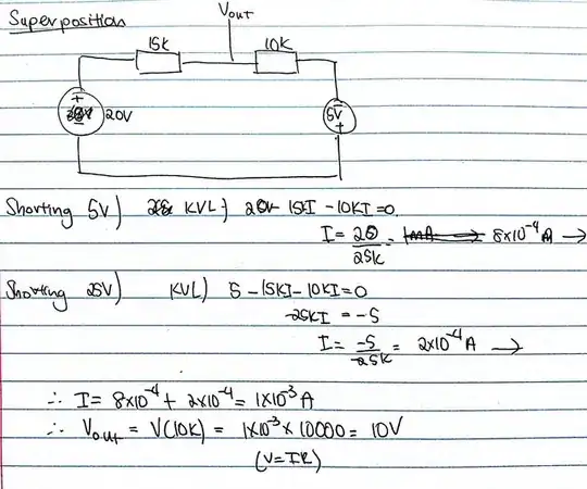
Confused, i tried a different method, superposition
By superposition and voltage division, the open circuit output voltage is
$$V_{out} = 20\,\mathrm{V} \frac{10\,\mathrm{k}\Omega}{10\,\mathrm{k}\Omega + 15\,\mathrm{k}\Omega}\, -5\,\mathrm{V} \frac{15\,\mathrm{k}\Omega}{10\,\mathrm{k}\Omega + 15\,\mathrm{k}\Omega} = 8\,\mathrm{V} - 3\,\mathrm{V} = 5\,\mathrm{V} $$
If this isn't clear, then let's redraw the schematic in full
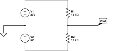
simulate this circuit – Schematic created using CircuitLab
and note that the node voltage \$V_{out}\$ is referenced to ground;\$V_{out}\$ is not the voltage across \$R_2\$.
For completeness, the Thevenin resistance is, by inspection, \$R_{th} = 15\,\mathrm{k}\Omega||10\,\mathrm{k}\Omega = 6\,\mathrm{k}\Omega\$
In the RHS of your equation you have 5V[15/(10+15)]. Why isn't it
5V[10/(10+15)] as the current still flows in the same direction as the
20V, from the positive to negative terminal?
With only the 5V source active (the 20V source is zeroed), the circuit is
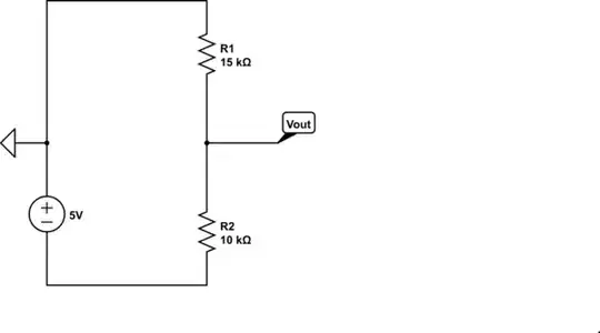
simulate this circuit
See that \$V_{out}\$ is the voltage across the \$15\,\mathrm{k}\Omega\$ resistor and the voltage across the 15k resistor is \$-5V \frac{15\,\mathrm{k}\Omega}{10\,\mathrm{k}\Omega + 15\,\mathrm{k}\Omega}\$ by voltage division.
If this isn't convincing, solve for the current
$$I = \frac{5\,\mathrm{V}}{10\,\mathrm{k}\Omega + 15\,\mathrm{k}\Omega}$$
and note that the current circulates clockwise; the current is down through the resistors thus, by KVL
$$V_{out} = 0\,\mathrm{V} - I\cdot 15\,\mathrm{k} \Omega = -5\,\mathrm{V} \frac{15\,\mathrm{k}\Omega}{10\,\mathrm{k}\Omega + 15\,\mathrm{k}\Omega}$$
as before.