Is there a simple way to tell axial inductors and resistors apart in through-hole type PCBs? I do find the color code on both very confusing. Is there an obvious difference that I am missing? As a beginner, I might just be overlooking something very simple.
Asked
Active
Viewed 2.6k times
16
-
1There is no universal reliable way. Most of the time you just know, or keep your stock properly labeled. – Olin Lathrop Apr 27 '14 at 12:15
-
Why not test for continuity with a multimeter? – sebascarra May 13 '16 at 23:29
-
@sebascarra what do you mean " continuity " ? resistance ? resistor and inductor, they all conduct, don't they ? – Long Pham Feb 23 '18 at 08:37
4 Answers
13
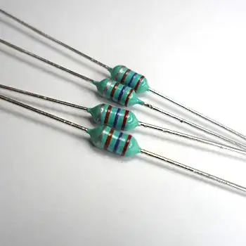
Axial inductors tend to be sea foam green, although some are pea green or even cyan. The cyan ones you can tell from 1% resistors because they have one fewer band.
Ignacio Vazquez-Abrams
- 48,282
- 4
- 73
- 102
-
Also, I don't know if all axial inductors have these, but the ends are more "pointy" than resistors – NothingsImpossible Apr 27 '14 at 11:26
7
The easiest, and most reliable, way is to look at the designator (and on a through-hole board, there is almost always a printed designator). If it says "L3", for example, it's most likely an inductor. If it says something like "R37", on the other hand, it's probably a resistor!
Beyond that, resistors sometimes have a specific body color, as Ignacio says, but not always. Dipped axial-lead inductors tend to have a specific kind of 'lumpy' look because of the wire, whereas resistors are fairly regular in their midsection.
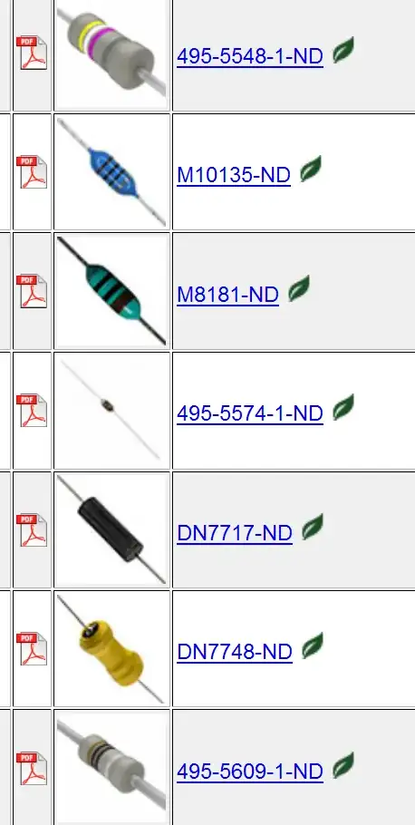
I suggest you go to a parametric search engine such as Digikey's, and search for a common value of axial-lead inductor (10\$\mu\$H will do) and look at the photos (you can mouseover the pictures to get a better view (more-or-less ignore the ones that are obvious 3D renderings of ideal 3D models). You can see that some are dipped as the photo above, some are molded like the old carbon-composition resistors, and some have a bit of shrink wrap around them. Here is a search that I did, not sure how long it will work, but with "in-stock" and "bulk + cut tape" restrictions, there are only two pages of parts, so you can look at all the variations in a couple of minutes, and quickly gain the kind of experience that would have taken many years not so long ago (and might still not have been exhaustive).
Spehro Pefhany
- 376,485
- 21
- 320
- 842
2
Is there a simple way to tell axial inductors and resistors apart in through-hole type PCBs?
Attach an LCR meter in-circuit, and see what comes out - is it more inductive, or more resistive? Sometimes, due to other components in the circuit, the LCR meter won't be able to get a meaningful reading - i.e. the L or R value will be nowhere close to what the value read from the bands indicate. Then you have to unsolder one side of the component and try again.
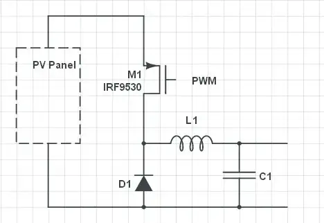
Most often, though, the difference is obvious if you can understand the function of the circuit you're looking at. You'll expect inductors to be in certain places (optionally or always), and that's where they'll be most of the time. Experience plays a big role here.
Visually, inductors are usually larger in diameter for a given length. They look like “oversized” resistors.
Kuba hasn't forgotten Monica
- 32,734
- 1
- 38
- 103
0
Classification by electronic color code value is a more accurate Visual Method. Color code is common for resistors and axial inductors. Always the color code, does not carry any electronic attribute (like Henry for inductance or Farad for resistance). it is just a value.
- Read (with your eyes) and translate its color code value to numerical value, either by using an online (web) Calculator or by consulting an Electronic Color Code table.
- Online calculators: (1) Resistor Calculator. Calculator.net. https://www.calculator.net/resistor-calculator.html , (2) 4 Band Resistor Color Code Calculator. DigiKey. https://www.digikey.com/en/resources/conversion-calculators/conversion-calculator-resistor-color-code , (3) others.
- Color Code tables: (1) Electronic color code. Wikipedia. https://en.wikipedia.org/wiki/Electronic_color_code (2) Resistor Color Codes. All About Circuits. https://www.allaboutcircuits.com/textbook/reference/chpt-2/resistor-color-codes/ , (3) others.
- Most common (numerical) values of inductance (as well as of capacitance) are decimals between 0 and 10, whilst, Most common values of resistance are integrals (and less frequently are decimals) bigger than 10. So if a value is between 0 and 10, then it is highly possible the electronic component is an inductor, else, if this value is bigger than 10 it is highly possible the e.component is a resistor.
- e.g.1. Let the numerical value be 0.000100, which equals to 100u. The value is in between 0 and 10. So, it is highly possible the e.component is an inductor, and the inductance is 100 uH.
- e.g.2. Let numerical value be 100. The value is bigger than 10. So, it is highly possible, the e.component is a resistor, and the resistance is 100 Ohm.
-
Ioannis Iliadis aka Ilousis - Hi, Thanks for trying to help. However the specific question is how to "tell axial inductors and resistors apart in through-hole type PCBs". The first 3 points in your current version don't answer that - they are just saying how to read a colour code, which applies to both axial inductors & resistors. It doesn't say how to tell them apart. I don't understand your last point (which seems to be addressing the specific question). Can you give examples of "values of inductance [...] are decimals between 0 and 1"? If I have a 100 uH inductor, how is that between 0 & 1? – SamGibson Apr 24 '23 at 12:54
-
-
Ioannis Iliadis aka Ilousis - Thanks for the update. Unfortunately I don't see how that helps to tell axial inductors and resistors apart. A 100 uH axial inductor has the colour code rings for "100". A 100 Ω resistor also has the colour code rings for "100". Neither of them is marked for "0.000100" so I don't see how that point helps to answer the original question :( Of course I do understand that 100 uH is < 1 H but as I said, I don't see how that helps with how to visually tell the 100 uH inductor apart from the 100 Ω resistor. Anyway, thanks for trying to help. – SamGibson Apr 24 '23 at 20:31
-
Right. I missed that the reference points, micro-zero for axial inductors and plain-zero for resistors, are different. Unfortunately color code doesn't support multipliers with exponential part lower than minus 3. Thanks. – Ioannis Iliadis aka Ilousis Apr 25 '23 at 07:03