8

I am considering implmenting an home automation system around my Raspberry Pi but I found the price and space requirement of inserting a Pi every place some control is required too much but the Cat5e cables required for this design is already installed during renovation. I have some PCF8574's, PCF8591's and SSRs lying around so is it possible to drive them using Cat5e cables?

All my Cat5e cables are already wired with TIA/EIA 568B pinout. They are part of my structural cabling and are not shielded, so higher line voltage is required. I am thinking sending power and I2C lines over the cable, with this pinout:

Pin 1 (Pair 1): SCL+
Pin 2 (Pair 1): SCL-
Pin 3 (Pair 2): SDA+
Pin 4 (Pair 3): +12V
Pin 5 (Pair 3): +12V
Pin 6 (Pair 2): SDA-
Pin 7 (Pair 4): GND
Pin 8 (Pair 4): GND

The power pin arrangement is same as 100BASE-TX PoE wiring so power rating will be the same too, and using of bidirectional differential signaling is found in 1000BASE-T which requires Cat5e.

Original I2C SCL and SDA lines are derived into two bidirectional differential pairs at TTL levels (the open-drain is not kept on the wire, but restored in the line termination/level shifting device that I am designing)

Any suggestion on that? Also, which chip should I use to convert I2C lines to the differential signalling? Please suggest chips with DIP through-hole option to me. I do not know how to handle SMT stuff.

EDIT

I found this chip, SN65LBC180, is it a good choice? How to wire it into a bidirectional unit? How to shift level (it is a BiCMOS part requiring TTL level but Pi drives at 3.3v CMOS levels) and make it open-drain-compatible?

EDIT 2

Commenters suggested RS-485 which appeared acceptable to me, but still the two differential pairs are required to be bidirectional and only two bidirectional differential pairs only. I am repurposing existing Ethernet cables.

EDIT 3

Since someone brought it up, I cannot use CAN. There is no way I can fit CAN onto RPi without sacrificing anything (SPI is occupied by a touchscreen, so no SPI to CAN converter)

I am aware of the limitation of I2C PHY so I am essentially trying to fit 1000BASE-T PHY to it - bidirectional differential signaling for SCL and SDA signals, but on top of that runs I2C protocol.

EDIT 4

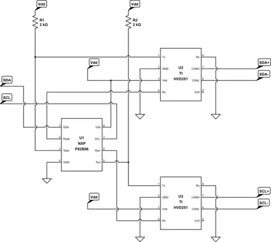
A new chip came to me: NXP P82B96 which splits I2C into 4 unidirectional lines, which in turn can be used to feed into SN65LBC180 through opto-isolation (Pi-side only) to form a 8-pin long-distance-ready signaling. Now I just need to figure out how to get power through the wire, or how to determine if the bus is sending and make the pairs bidirectional.

EDIT 5

From the suggestions of answers, I think I need to change the power pinout a little:

Pin 1 (Pair 1): SCL+
Pin 2 (Pair 1): SCL-
Pin 3 (Pair 2): SDA+
Pin 4 (Pair 3): +5V
Pin 5 (Pair 3): GND
Pin 6 (Pair 2): SDA-
Pin 7 (Pair 4): GND
Pin 8 (Pair 4): +12V

I2C differential signaling voltage is TTL. The +5V over pair 3 comes from the Pi, unbuffered but fused. The +12V over pair 4 may not be present is only used to drive some high-power devices. If needed the device may use its own power supply and leave both rails hanging unconnected or supply its own higher voltage but use the 5V rail.

SCRATCH THAT

Pinout is still my original design, which is 802.1af compatible.

Maxthon Chan
  • 2,853
  • 1
  • 16
  • 33
  • 4
    Why not RS-485? It's industrial, reliable standard. – Kamil Apr 23 '14 at 12:35
  • Pi does not have RS485 and I want the interfacing circuit as simple as possible. Also I need PCF8574 which, from my experiments, can drives my SSR on reliably with 5V supply voltage. – Maxthon Chan Apr 23 '14 at 12:45
  • While RS-485 itself is bidirectional, it does not do bidirectional on the single-ended side. – Ignacio Vazquez-Abrams Apr 23 '14 at 12:45
  • @IgnacioVazquez-Abrams I am repurposing existing Ethernet wiring... I can use RS485 interface chips but RS485 can still only be sent over pins 1/2 and 3/6, and pins 4/5 and 7/8 are still 12V power rail and ground pins. – Maxthon Chan Apr 23 '14 at 12:48
  • But that doesn't make it suitable for your purposes. – Ignacio Vazquez-Abrams Apr 23 '14 at 12:49
  • One reason that SCL and SDA are open-collector is that they're both bidirectional -- they can be driven low by either the master or the slave. How are you managing this in your interface design? While I2C is a synchronous protocol, and *can* be run over long cables by slowing it down and using appropriate filters, there are much better choices for cable communications, such as CANbus, RS-485, or even asynchronous RS-422. – Dave Tweed Apr 23 '14 at 12:49
  • How long is your CAT-5 cable? I have something similar with 20m (~60ft) I2C connection from the basement for temperature monitoring. It works well with cheap unshielded phone cable. No level shifting, just two 5V microcontrollers connected via i2c. – Kamil Apr 23 '14 at 12:50
  • @Kamil Somewhere around 10 to 30 meters, somewhat hostile alien crosstalk environment. The cables can run 1000BASE-T reliably, though. (and that is why I am trying to use signaling that is most similar to 1000BASE-T and 100BASE-T PoE) – Maxthon Chan Apr 23 '14 at 12:53
  • You should try low frequency I2C and connect that and just try. If you have scope - you can see what is going on on SDA/SCL lines on both sides. – Kamil Apr 23 '14 at 12:55
  • If you intend to use Ethernet cable have you considered just using Ethernet for communication? If part of the requirement is power and communication in one cable you could use PoE. – mjh2007 Apr 23 '14 at 12:56
  • @DaveTweed That is why I am using bidirectional differential signaling. I am pulling the bus up at the remote end (terminating open-drain section) and use open-drain interface at controller side. – Maxthon Chan Apr 23 '14 at 12:57
  • @mjh2007 I was planning on just Ethernet everywhere but it turned out to be too expensive for me. That is how I had the idea of using running similar signalling but use a different protocol - use 1000BASE-T styled bidirectional differential signaling on two pairs, and 100BASE-T PoE styled power on the other two. – Maxthon Chan Apr 23 '14 at 13:00
  • @Kamil I don't have a scope and I don't want the structural cabling alien crosstalking driving my I2C devices haywire. That is why I need differential signaling. – Maxthon Chan Apr 23 '14 at 13:02
  • Instead of rpis you could keep cost down by using a microcontroller with built in ethernet or an spi ethernet module and use the cables are normal ethernet with poe. – Grant Apr 23 '14 at 13:06
  • @Grant They are not quite available here and quite expensive. I also have a size limit. I need to fit the entire thing into my existing structural cabling switch box. – Maxthon Chan Apr 23 '14 at 13:09
  • Anything wrong with using CAN? – Synchrondyne Apr 23 '14 at 13:09
  • @PeterK RPi don't have those, and I need to keep the size minimal. – Maxthon Chan Apr 23 '14 at 13:18
  • 5
    If you're so dead set on doing what you said you were going to do originally, why did you even come here and ask about it? – Matt Young Apr 23 '14 at 13:33
  • @MattYoung I need suggestion on designing the interface module, including the Pi side and device side. Device side will be no bus - one interface module to one device, and Pi side is on a bus. – Maxthon Chan Apr 23 '14 at 13:37
  • Do you even need a communication protocol? What is going to be on the "device side"? Could you use the ethernet cables to simply control relays, and have all the i2c stuff at the rpi's end? – Grant Apr 23 '14 at 14:50
  • @Grant I am not exactly confident about how much power can the wires hold. – Maxthon Chan Apr 23 '14 at 14:56
  • 2
    @maxthonchan Cat5 ethernet wires can safely handle 360ma at 50V (http://en.wikipedia.org/wiki/Power_over_Ethernet#Power_capacity_limits). You can easily get solid state relays that draw <10ma at 3-32V on the input side, so well within the safe specs. – Grant Apr 23 '14 at 16:04

8 Answers8

19

Trying to do with with IIC is a bad idea. IIC is really meant for communication between chips on a single board. Since the maximum required current to pull a line low is limited, the lines are relatively high impedance (a few kΩ). This means they can pick up noise easily, which is a serious issue when running in unshielded cable in the walls possibly right next AC power wires.

I would use CAN for this. CAN uses a single twisted pair pulled together with only 60 Ω at any one point, and the signal is differential. That means most of the inevitable common mode noise that will be picked up due to capacitive coupling can be cancelled by receivers. CAN running at 500 kbits/s can cover something the size of a ordinary house.

Many microcontrollers are available today with CAN built in. You usually need a separate physical tranceiver chip (like the common MCP2551), but the lowest few layers of the protocol are implemented in silicon in the CAN peripheral. The firmware interacts with the CAN bus at the level of sending and receiving complete packets. The collision detection and retry, checksum generation, details of the bus packet signalling, received checksum validation, and clock drift adjustment are all handled for you.

Don't fall for RS-485. That's a relic from a bygone era. It also uses a single differential signal like CAN, so also has good noise immunity. However, people usually fall for RS-485 because it looks "simpler". This is only because they don't look at the whole system. First, it's not really any less complex electrically. You will still need some kind of transciever to drive and receive the differential signal. Whether you have a RS-485 transceiver connected to the microcontroller's UART, or a MCP2551 connected to the CAN peripheral is pretty much irrelevant in terms of cost and hardware complexity. The big difference is that RS-485 leaves you at the raw byte level (via the UART). This means to implement any meaningful and robust system, you have to invent your own protocol to handle collision detection, decide how to handle retries, packetization, checksum generation and checking, flow control, etc. You can use a single master architecture, but getting the details right is a lot more tricky than people think that haven't analyzed all of them carefully. With CAN you just send and receive packets, and the hardware takes care of the details.

Olin Lathrop
  • 310,974
  • 36
  • 428
  • 915
  • I don't have CAN built in to RPi, I don't have CAN interface, I cannot afford them and I cannot fit them into existing housing. So, NO CAN. I am converting IIC to and fro differential signaling to avoid that very pitfall of crosstalk and resistance. The conversion and IIC device share one single board. – Maxthon Chan Apr 23 '14 at 13:21
  • @Max: A microcontroller with CAN will be cheaper, smaller, an take less power than a RPi. If these node are mostly sensors and the like, a RPi is overkill anyway. – Olin Lathrop Apr 23 '14 at 13:27
  • uC's does not have adequate computational power to run the other side of the system. Although I do have a touchscreen on the system that is just for emergency overriding, all commands are sent over home network to the Pi over HTTP (with quite a fancy AJAX-driven UI), and Pi handles all authentication and other stuff. – Maxthon Chan Apr 23 '14 at 13:31
  • 3
    @MaxthonChan You can get cheap controller ICs that convert CAN to SPI and/or I2C to interface with your RasPI. [Example from Microchip](http://ww1.microchip.com/downloads/en/devicedoc/21801d.pdf). – Synchrondyne Apr 23 '14 at 13:38
  • If that is your suggestion, then please tell me how can I drive my SSR? Currently I have one receive board with the diff interfacing chip, a 7805 and a PCF8574, and it drives up to 8 SSRs. (and usually I have two or three) – Maxthon Chan Apr 23 '14 at 13:43
  • @PeterK Please suggest some I2C examples if you are trying to steer me into repurpose the wires to carry CAN signaling. I do not have any spare SPI bus slots available. – Maxthon Chan Apr 23 '14 at 13:44
  • I ended up using CAN PHY, but not the protocol itself. Protocol is still I2C, though. – Maxthon Chan Apr 23 '14 at 14:35
  • @OlinLathrop Would you think CAN is suitable for an elevator for say about 16 floors ?The CAN would be used mainly to log calls from the car or each landing.Not looking to sidetrack the thread,just looking for a "gutfeel" reply. – EmbSysDev Apr 24 '14 at 13:02
  • @EmbSysDev That is not my use case - I have a clear definition of master and slave devices: the Pi is the bus master that receives instructions over Internet, authenticate it, and forward it to the bus. The modified switch (or light dimmer) is slave, that performs actual work (switching an SSR, etc) upon receiving an instruction addressed to it. I don't think CAN is appropriate here but I2C is. I2C do have its own issues (long wires with harsh alien crosstalking) and that is what I am trying to overcome. – Maxthon Chan Apr 25 '14 at 18:49
  • @Maxt: If that's what you want to do (one main controller with multiple small devices), then I really don't see the issue with CAN. You interface the RPi to the CAN bus once, then each slave is quite simple and small. You can either have the RPi talk to a CAN micro, or control the bus directly with something like a MCP2515 (CAN controller with SPI interface). If the RPi does't have SPI, then you can still bit bang it with 4 I/O lines. I think you're going to have flaky problems with the IIC bus as you propose. – Olin Lathrop Apr 25 '14 at 19:00
  • @OlinLathrop have already read the documentation and forum posts regarding bit banging CAN even with a PHY chip - impossible if the system is multitasking due to timing jitters - which is required on my Pi as it is also authenticating (cryptography work, CPU intensive) and forwarding instructions. SPI and UART are occupied so only I2C is available with hardware support to prevent jitters. – Maxthon Chan Apr 25 '14 at 19:08
  • @OlinLathrop Also I have a size constraint: 5cm by 5cm by 3cm max or it won't fit in existing fixtures. I can make a board with four or five chips that fit in this constraint and works with I2C protocol (probably CAN PHY) – Maxthon Chan Apr 25 '14 at 19:11
  • @OlinLathrop You should read my own answer which is pretty much my final design, use CAN PHY to send I2C protocol. NXP have a chip that breaks I2C bus into two pairs of UART lines, which in turn can be carried over CAN PHY as two differential pairs. This design exists even in NXP AN's. – Maxthon Chan Apr 25 '14 at 19:15
  • @OlinLathrop The interface consists of only three chips (seven if optocouplers are required, only true on Pi side which have no size constraint) so this makes an extremely tiny 4-chip slave side device. – Maxthon Chan Apr 25 '14 at 19:18
7

I2C is not the way to go. CAN trancievers cost a dollar each, and you can use them as uart trancieves and write your own protocol so you dont need a can compatible micro of you dont want to use the full can stack.

I always feel a little uncomfortable when I see cat5 conductors run in paralel for more current. It bugs me because if one conductor breaks the other will carry full system current. The cat5 current ratings are very conservative so the odds of a fire are fairly low but I just dont like the possibility.

The safe way to do it is to have a polyfuse on both power rails and join the grounds at the supply, and connect each device to one and only one set of power/ground. That way if one wire fails, the devices using that line lose power instead of one line being forced to carry the power of two.

A lot of people like to put power and ground in both twisted pairs for EMI reasons instead of having one power pair and one ground pair. If you have two power/ground pairs the power line will be closer to ground, and the fields will cancel out, reducing any transmitted or recieved radio waves from the power lines. Unnecessary, but nice if there is lots of electrical noise humming about.

12V in my opinion is too low for power distribution when 24v is still reasonably safe and much more efficient.

EternityForest
  • 691
  • 4
  • 6
  • My solution is somehow based on that. I use the NXP splitter chip to split I2C bus into a pair of Tx/Rx's (both SDA and SCL) and multiplex them as UART using CAN interface chips. This gives me two twisted pairs carrying I2C SDA and SCL lines, wired to Cat5e TIA/EIA568B pins 1/2 and 3/6. – Maxthon Chan Apr 24 '14 at 04:48
  • That should also work, the only problem is you need your NXP chip, two can trancievers, and your actual i2c I/O chip. Thats five chips per board, and last I checked the NXP chip was more expensive than at atmega328, but that might have changed. It will work and the programming will be simple because it's i2c, but using UART over CAN is cheaper for a bit more work. – EternityForest Apr 24 '14 at 05:32
  • The Pi-side interface board have 7 chips - NXP I2C buffer/splitter, two CAN PHY and four optoisolators. The device-side is a 4-chip module - NXP I2C buffer/splitter, two CAN PHY and the PCF8574/8591. – Maxthon Chan Apr 24 '14 at 07:17
  • I found a 4-channel optocouplerwhich will reduce the Pi-side circuit to a 4-chip module. – Maxthon Chan Apr 24 '14 at 07:54
  • Rethinked the power pins, I am sticking to my original design, using a power pair and a ground pair. That is compatible to 802.3af although I redefined signal pins to SCL and SDA. – Maxthon Chan Apr 25 '14 at 19:23
3

If the automation is simply turning things around the house on and off, I would simplify this by:

  • Keeping all the "brains" in one place. Use I2C I/O expanders if needed, but keep them all with the raspberry pi. You'll also need appropriate hardware to make sure you aren't trying to get too much current from the pi's GPIO pins.
  • Use the ethernet cables to simply drive relays. You can build your own board, or get panel mountable 120/240V solid state relays that will mount in an electrical box. The wires in Cat5 ethernet cables can handle up to 50V at 320mA each, which is more than enough to drive a relay. In fact, you could drive 7 relays from a single cable (plus one wire for ground). Or leave one wire for an unswitch 12V output, so you can install a manual switch as well. If they are really long runs, you may have to account for voltage drop, but you can get relays that will switch at 3-32V. 12V should be more than enough, even with voltage drop.
  • You will also want to consult local building codes for advice about mixing high and low voltage cabling in the same box.
  • Simple switches can also be done through the ethernet cables, again up to 7 per cable, and simply wired to the pi's inputs. Voltage drop may be a concern for really long cables.
  • You may also want to use optoisolators to protect the pi from damage.
  • For the few devices that need more than a relay (like a control panel) use the ethernet cables as actual ethernet. It shouldn't be a huge expense if there aren't many of these devices. They could either be another pi, or a microcontroller with ethernet.
Grant
  • 1,703
  • 2
  • 15
  • 22
  • I am not exactly sure what my end users' needs will turn out to be. She is moody and changes her mind very fast. I will have to be able to respond fast enough. That is why some sort of basic protocol (I2C here) is used over the wire. – Maxthon Chan Apr 24 '14 at 04:53
2

schematic

simulate this circuit – Schematic created using CircuitLab

EUREKA! Figured it out! (untested, will test it out this weekend)

The interface chips are NXP P82B96 I2C buffer/splitter and 2 TI SN65HVD251P CAN bus interface chips. Essentially, I am running I2C on CAN PHY.

P82B96 understands I2C protocol and handles bus arbitration for me, and gives me separate Tx and Rx pins that can be tied together. I feed those into SN65HVD251P CAN transceiver and it gives me the bidirectional differential pair to send over wires.

Power pins comes directly, unbuffered from my Pi's 5V rail. (I will not use 12V signaling voltage and power for a while)

Maxthon Chan
  • 2,853
  • 1
  • 16
  • 33
  • Sorry, but no. What that will allow you to do is connect _two_ I2C units at some distance from each other. It will not allow you connect more than 2. – WhatRoughBeast Apr 23 '14 at 15:25
  • @WhatRoughBeast I have looked that up on NXP documentation and it says that this is a viable solution (and it somehow made its way into their AN) but to me, a point-to-point is okay as my design itself is asking for one pair of conversion units per Cat5e segment. – Maxthon Chan Apr 23 '14 at 15:36
  • CAN is wired-or and bidirectional just like i2c. I see no reason that this should not work with as many devices as you want on the bus. I've seen the app notr he mentions. It does appear to describe a bus, not a point to point. – EternityForest Apr 24 '14 at 05:28
  • @WhatRoughBeast - CAN is multidrop, I haven't looked too closely at what the OP is doing, but it should be theoretically possible. – Connor Wolf Apr 26 '14 at 09:23
1

Regardless of the merits of IIC at the chip level, your proposed implementation is going to be very difficult. The problem is bus arbitration. Although multiple units can be paralleled using, for instance, RS485, the big question will be:

How does any unit know whether it can take control of the bus in order to send data?

In IIC, with open drain signal lines, bidirectional transfer is easy - but with tristate busses you need some way to ensure that only one unit attempts to drive the bus at a time. This will be tricky. You can do it, particularly if you establish a single master and require that all the slaves have rigid timing constraints on sending data, and that they only send data if requested by the master, but this will require considerable effort on your part in designing the interface boards for the master and the slaves.

As for physical drivers/receivers, RS485 will do you fine, and there are lots of interface chips available. Just Google.

WhatRoughBeast
  • 59,978
  • 2
  • 37
  • 97
1

I don't know if you're interested in a premade solution as opposed building your own circuit, but I thought I'd point out that Pololu sells these I²C Long Distance Differential Extender boards made by SJTbits, which seem to do pretty much exactly what you're looking for. (Full disclosure: I work for Pololu.)

Even if you don't want to use it directly, maybe looking at the circuit it uses might give you some ideas. You can see the schematic in the datasheet; it uses an NXP PCA9600D buffer, TI AM26LS31CDR differential line driver, and TI AM26LS32ACDR differential line receiver.

kwc
  • 511
  • 3
  • 9
1

I know this is a bit old and a solution seems to have been settled on somewhere amongst the replies, but I had this suggestion to offer. There are devices like the PCA9614/5/6 from NXP that I'm looking at right now as a solution for a more robust long distance I2C bus (PCA9614 2-channel multipoint Fast-mode Plus differential I2C-bus buffer). Esentially it's true that it's becoming something other than true I2C, but at the ends of the bus it's invisible to the devices. This particular family translates the signals into 2 bidirectional differential pairs, and there are also similar devices as have been already mentioned in the comments, that translate to 4 unidirectional differential pairs. Translating to just 2 pairs allows you to use CAT cable and still have 2 pairs for power/ground.

Mahendra Gunawardena
  • 1,746
  • 1
  • 14
  • 18
John Lewis
  • 41
  • 3
0

Thumbs up! I'm currently trying to solve pretty much the same problem. I'm also trying to use I2C over cat5 for home automation with my custom pinout. The reason is cost, I want it be very cost effective and I2C components still at least 5 times cheaper than even attiny13 uC (AFAIU uC is required for CAN and RS485).

1) Currently I am just in a process of trial for the first part of a system and now I'm succeed with 15m long cable with 5V and dirrect SCL&SDA connection! I use PCF8574 and 2 relays to trigger my room lights. Pinout is

1
2 INT
3 +5V
4 SCL
5 SDA
6 GND
7
8

2) I do understand that it will not afford a couple more relays or an extra 10 meters... A voltage drop is significant (from 5.5 to 4.7). So for the voltage drop problem I'm going to put 12V on a line instead and add 5V voltage regulators on boards to keep fine voltage everywhere regardless of entire line drop. I'll put additional power supplies during the future lines anyway.

3) The signal itself can be improved using P82B96 or cheap P82B715 without splitting to differential lines. An NXP itself uses Cat5 in some presentations but I can't find their pinout. An important part here is that they clearly use signal lines in different pairs... e.g. one pair is GND+SDA the other is VCC+SCL.

4) Another interesting point - this buffers can simply raise an amplitude up to 12V to increase noise resistance. So, I'll probably try to put 12V on on a signal lines too and that should allow to put a pullups dirrectly from 12V wire... But that will force me put something like P82B96 on each device.

As you may noticed, I also use separate interrupt line... Master is currently on arduino board connected to PC. The primary master software will be on a 24x7 PC anyway, so arduino just translates signal and handles interrupt. I can send specific configuration for onboard interrupt handling e.g. to handle convenient switch toggle via interrupt... That allows me forget about any delays when toggling light manually. Interrupt handling is additional advantage of i2c.

So my idea is that I2C is simple enough to be applicable in <=100m city apartment cabling. Instead of going to differential signal I hope I'll able to reduce extra frequency instead.

I like your idea to put both 5V and 12V since this reduces need in regulators and reduces cost... the whole idea of multi-wire bus it to reduce cost of endpoints, I'll also consider this for new pinout :)

  • 1
    This is more of an extended comment on the question than an answer, since your situation is not the same as the OP's: different master hardware, different signaling scheme. But it's closely related enough that I'm going to let it stand. – Dave Tweed Jul 13 '14 at 11:22