Apparently, the gain of this Op Amp is one, but I can't see how I could figure that out. Can someone help?
Apparently, the gain of this Op Amp is one, but I can't see how I could figure that out. Can someone help?
The gain of the op amp is very high, typically 100k to 1M or more. The gain of the circuit in this case is very close to 1.
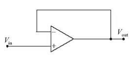
For now, let's imagine a nice ideal opamp with 0 offset voltage, infinite gain, etc. Think of what would happen if the gain weren't 1. Let's say you drive Vin to 3.0 V. The opamp will then drive Vout to also be 3.0 V.
Now imagine what would happen if it didn't. Let's say the opamp only drove Vout to 2.9 V. That means the positive input of the opamp is 3.0 V and the negative input 2.9 V, for a total differential input signal of 100 mV. Multiply that by the gain of the opamp, and that's what it will try to drive its output to. Obviously it will try to drive Vout as high as it can in this case. However, eventually Vout gets to 3.0 V, the differential input to the opamp is then 0 and it no longer tries to drive Vout high. If Vout went a tiny bit higher, the differential input to the opamp would be a little negative, which would make it try to pull Vout low. Put another way, the opamp will try to pull Vout down if it is above Vin, and up if it is below Vin. Eventually, assuming nothing is externally holding Vout fixed, Vout converges to be the same as Vin.
This can be described mathematically quite easily too. What a opamp does is basically:
Vo = G(Vp - Vn)
Where Vp is the voltage at the positive input, Vn the voltage at the negative input, Vo the output voltage, and G the gain of the opamp. As I said above, G is usually a large number, like 100k to 1M or more.
From how the circuit is wired, we get:
Vn = Vo
Vp = Vin
Substituting these into the first equation, we get:
Vo = G(Vin - Vo)
Solving for Vo as a function of Vin yields:
Vo = (G / (1 + G)) Vin
Note that G / (1 + G) is basically 1 for large values of G. Even if G is only 100k, then the overall gain of this circuit is 0.99999, which is 1 for the vast majority of practical purposes.
Actually your premise is not quite correct. The overall gain is not 1, it's \$ \frac{1}{1 + \frac{1}{G}}\$, where G is the gain of the op-amp. If G is very high, such as for a precision op-amp near DC, then the gain is very close to 1. But an LM324 (say) at 30kHz has a gain of only about 40, so the gain is closer to 0.975.
\$V_{OUT} = G (V_{IN+} - V_{IN-})\$, so if \$V_{IN-}\$ = \$V_{OUT}\$
then \$V_{OUT} (\frac{1}{G} +1) = V_{IN+}\$, and \$\frac{V_{OUT}}{V_{IN}} = \frac{1}{1 + \frac{1}{G}}\$
Apply the basic rules of Op-Amps with negative feedback:
The op amp will try to match the voltage at the input terminals by adjusting the output voltage.
Assume Vin+ = Vin- (from the basic operation of an Op-Amp)
Vin- is tied directly to Vout, thus Vout=Vin-=Vin+
Define gain as G = Vout/Vin+ = 1
but I can't see how I could figure that out. Can someone help?
Step by step assuming an ideal op-amp with negative feedback present:
(1) \$V_+ = V_{in}\$ by inspection
(2) \$V_- = V_{out}\$ by inspection
(3) \$V_- = V_+ \$ due to negative feedback and 'infinite' op-amp gain
Thus
$$V_{out} = V_{in}$$
Now, the above assumes you're aware that \$V_- = V_+ \$ for an ideal op-amp with negative feedback.
If you're not aware of this, below is the justification.
Assume the op-amp has finite voltage gain \$A\$
$$V_{out} = A(V_+ - V_-)$$
Now, connect the output of the op-amp to the inverting input with some attenuation \$b\$
$$V_- = bV_{out}$$
Substitute into the previous equation
$$V_{out} = A(V_+ - bV_{out})$$
Gather terms and simplify
$$V_{out} (1 + Ab) = AV_+$$
Solve for \$V_{out}\$
$$V_{out} = \frac{A}{1 + Ab}V_+$$
Which implies
$$V_- = \frac{Ab}{1 + Ab}V_+ $$
Now, take the limit as the gain \$A\$ goes to infinity
$$\lim_{A \rightarrow \infty}V_- = \lim_{A \rightarrow \infty}\frac{Ab}{1 + Ab}V_+ = V_+ $$
Thus, for an ideal op-amp (infinite gain) with negative feedback, we have the fundamental result
$$V_- = V_+ $$
Negative Feedback can take a little bit of understanding. Consider this diagram: -
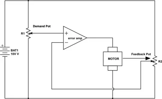
simulate this circuit – Schematic created using CircuitLab
From left to right we have: -
If the error amp had low gain (output = difference between +input & -input), by the time the motor had moved the spindle in the right direction a bit, the output of the error amp might only be a volt and the motor would stall. This tells you that half a job has been done and the two pots are nearly at the same point - if the demand pot was set at 7V, the feedback pot will have moved to either 6V or 8V before the motor stalled.
However, if the error amp gain were increased ten times, the error would reduce by ten-fold. Keep on increasing the error amp gain and you should be able to see that the error gets proportionally smaller. Error amp gain of a million or so and the error is so small it's barely worth considering.
This is a unity gain op-amp in all but name.