5

I'm going to buy a PC tower case that has only one LED intended to be used as the power LED, and no separate HDD LED is available. My intention is to have that single LED lit at about 50% of its intensity when the PC is turned on and there's no HDD activity, and to have it lit at about 100% brightness to indicate HDD activity. Thus, it would become some kind of a "hybrid" LED indicator.

I'm not sure how the LED outputs are actually constructed on PC motherboards, so my initial thoughts were to use optocouplers and stay on the safe side. Here's the citcuit I had in mind, but please keep in mind that I'm nowhere close to being an expert when it comes to designing electronic circuits:

Initial design, with no resistors values calculated yet

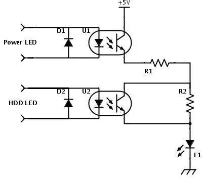
I haven't calculated the resistor values yet, though having 220 ohms in all places should be fine -- or at least it looks to me like that. Also, I haven't looked yet at the exact optocouplers and their CTR values. Could the whole thing be made simpler without risking to damage the motherboard, which is quite expensive?

Please advise. Thank you!


UPDATE #1: Based on an answer below, here's how a simplified schematic may look like. It would also handle ACPI sleep states when there's no +5 V from the PSU except the +5 VSB, and the power LED blinks in such cases. Would it work?

Simplified design, also capable of handling ACPI sleep states


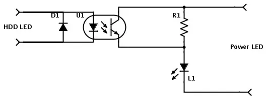
UPDATE #2: Yup, it should work as pointed out below, and it also cuts the required number of components in half. I'll try it out once my tower case arrives so I can see what brightness levels work well, and I'll report back.


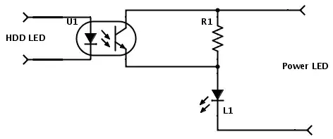
UPDATE #3: The diode D1 is redundant, as the LED inside the optocoupler can't be damaged by the reverse voltage coming from the motherboard's HDD LED output. Simplified schematic follows below.

Even more simplified design

dsimic
  • 53
  • 1
  • 6
  • 1
    It would be much simple if you could replace that LED with a bi colour one. For example red-green: green when powered, yellow when HDD activity (both on). – Cornelius Apr 21 '14 at 08:47
  • I've already thought about that option, too. However, using a bi-color LED would mean that negative outputs of power and HDD LEDs would be tied together, and I have no idea whether those are floating grounds or not, what's pretty much eliminating a bi-color LED as an option. Also, I must say I'm not that much into having a "compound" color when there's HDD activity. – dsimic Apr 21 '14 at 08:52
  • Common Cathode 2 Color on 3 pin would work –  Apr 21 '14 at 10:42
  • According to http://hardforum.com/showthread.php?t=1125598 and http://case-mods.linear1.org/hdd-header-hardcore/ , ground is what's switched for moterboard LED outputs, so tying the grounds together might be risky. Not worth trying that on an expensive motherboard, IMHO. – dsimic Apr 21 '14 at 10:56
  • Then see if VCC is shared between the two LEDs instead and use a common-anode two-color LED. You're only out of luck if the mobo puts the LED in between the current-limit resistor and the drive pin. – Mike DeSimone Jun 26 '14 at 04:16
  • BTW, one last mod you can make to your latest circuit is to replace R1 with a small trimpot. Then you can adjust brightness on the fly. – Mike DeSimone Jun 26 '14 at 04:17
  • As for seeing how your motherboard is wired: see if you can get continuity between the black wires on the ATX connector and either pin on the LED connectors. If so, then you can use a common-cathode two-color LED. If not, then check for continuity with the other power lines (probably red [5V] or orange [3.3V]). If you get it, then you can use common-anode. – Mike DeSimone Jun 26 '14 at 04:21
  • Finally, some SMD two-color LEDs are four-terminal and have no common pin. – Mike DeSimone Jun 26 '14 at 04:22
  • Sorry for my delayed response. Yes, it is possible to examine the way motherboard runs the LEDs, but my intentions are to build a universal solution which doesn't depend on a way particular motherboard works. And I'd like to avoid two-color LEDs. :) – dsimic Aug 16 '14 at 12:10
  • Using a trimpot is always a good and pretty much the most flexible option. However, in order to keep the additional "control board" as small as possible, using a plain resistor should be better -- after its value is determined empirically, of course. – dsimic Aug 16 '14 at 12:14

3 Answers3

4

Seems like it would be simpler to use only one optocoupler, and shunt it with a resistor for the (dim) power-on states.

schematic

simulate this circuit – Schematic created using CircuitLab

I also think you need more than a 2:1 difference in current for it to be obvious (given the eye's logarithmic response), more like 10:1 for a modern bright LED. You may have to experiment a bit.

As one data point, car tail lights have about a 10:1 ~ 20:1 brightness difference between running and brake lights.

Spehro Pefhany
  • 376,485
  • 21
  • 320
  • 842
  • Thank you for responding so quickly! Actually, motherboard's power LED output isn't the same as having +5 V from the PC power supply, as the power LED also indicates ACPI sleep states via blinking etc. However, your solution is *much* better even in that case, as while the PC is inside one of the ACPI sleep states there's no +5 V from the PSU except the stand-by voltage (VSB) which isn't easily accesible without splicing into the wiring etc. Regarding the brightness difference, sure thing, 50% value was off the top of my head and I'll experiment a bit and report the actual results. – dsimic Apr 21 '14 at 09:26
  • Actually, your solution isn't covering the blinking in ACPI sleep states and similar conditions. Could the actual power LED output be used instead of the external +5 V supply, with a resistor in series to the LED which would be shorted by the optocoupler's output? – dsimic Apr 21 '14 at 09:35
  • 1
    With a resistor in parallel that should work. Dim the power LED unless the HDD is active. My answer is edited. – Spehro Pefhany Apr 21 '14 at 09:42
  • Great, thank you! I've also added a simplified design in my original question, while you were editing your reply. – dsimic Apr 21 '14 at 09:47
  • Beside properly handling the ACPI sleep states, the number of required components was cut in half, what's also great. :) – dsimic Apr 21 '14 at 09:52
  • 1
    Yup, 2 parts total is pretty reasonable. I don't think you need the diode D1 on the input. – Spehro Pefhany Apr 21 '14 at 09:55
  • Exactly, the LED inside the optocoupler can't be damaged by receiving a reverse voltage which is already tailored for a LED. Once again, thank you! – dsimic Apr 21 '14 at 09:58
  • 2
    Why not punch a 5mm hole in front cover for HDD LED? –  Apr 21 '14 at 10:45
  • 1
    That would ruin the aesthetics of the case, as it has a front door and there's little to no space for adding one more LED. Also, modding the case mechanically would require more effort than adding some circuitry. Here's the description of the case: http://www.fractal-design.com/home/product/cases/define-series/define-xl-r2-black-pearl . – dsimic Apr 21 '14 at 17:25
1

Seeing as there was no recommended answer ...I'm not sure if it would help in this regard but I did something similar that could be beneficial in your needs. It will also take account for any sleep states as well accordingly and is based off a single reverse-biased PnP transistor. I used a 0.15uf polyester capacitor for a more reactive change instead but an electrolytic works just as well if needed. VCC is either of the positive leads from the Power or HDD led from the motherboard header and bases off a negative pull from the ground leads.

From testing, the motherboard I used actually supplies a steady 5v power from the positive leads but instead pulls different voltages down the negative leads, which is what it was based on.

The whole end result is that it essentially 'turns off' the power LED during activity in favour of the HDD LED. It will not combine colours at all. A larger capacitor will result in a longer 'off time' for the power led and introduce a 'fading transition' with large enough cap between them instead but will also raise the cutoff limit for intermittent HDD activity.

Source: Combine HDD and PWR status LEDs into one. - Overclock.net

Edit: Being as I need 50 reputation to clarify the functionality of this. The method it works is based on current starvation. This circuit assumes you are using the current limited 5v input from one of the two HDD/PWR LED headers. Otherwise a 5v source with an inline 100-150ohm resistor works just as well such as powering the front panel through the 5v USB instead. When the HDD LED activates it pulls current from the transistor base and lets through the current that is otherwise going to the PWR LED through the collector. This essentially shuts off the POWER LED since there is little to no current going through it during such activity.

Chozo4
  • 3
  • 1
Chozo4
  • 11
  • 2
  • Sorry for my delayed response. This looks quite interesting, but I'm not entirely sure how does this circuitry turn off the power LED during HDD activity? Please excuse me if I'm missing something obvious, but an additional explanation would be appreciated. – dsimic Aug 16 '14 at 12:29
  • @Chozo4 I've noticed that you have created a second account and edited your answer from that new account. You should be able to edit your answer from the original account without having to create a new one. – Nick Alexeev Oct 06 '14 at 06:28
1

schematic

simulate this circuit – Schematic created using CircuitLab

You can do this using just the power LED on the case, but you only need one component, a 1.5K resistor in line with the negative lead of the motherboard's PWR LED output pins. Connect the motherboard's PWR LED (+) and HDD LED (+) outputs together, and run them to the case PWR LED (+). Connect the case LED (-) to both the motherboard HDD LED (-) and the other lead of the resistor. What you end up with is a dim, always-on power indication and a bright flashing HDD indication on the same LED. I messed up originally and tried to put the resistor in line with the positive lead, but I was forgetting that CMOS can only sink current, not source. So the positive lines are always on and the negative lines are the switched ones. (This took me 3 days of trial and error to figure out, so I thought it best to share and spare everyone else the pain. It was also a quite embarrassing and humbling experience, being a retired RF engineer. What was it Gandalf said? "Absurdly simple, like most riddles when you see the answer!")

Dave
  • 11
  • 2
  • This is a nice approach, thank you! However, I'd prefer to keep the different LED circuits 100% electrically separate, just to be on the safe side, which is why the original idea was to use an optocoupler. – dsimic Aug 03 '23 at 03:35
  • Just to add, keeping the LED circuits 100% separate is probably rather redundant, but I think that being extra careful mey be worth it, especially with the computer hardware prices these days. :) – dsimic Aug 03 '23 at 03:37