2

schematic

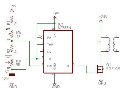
simulate this circuit – Schematic created using CircuitLab

I made this simple NE555 Flyback driver. I used a 9V Battery to power the NE555 and a 24V 6A power supply to power the flyback. The problem is that the MOSFET gets very hot in a few seconds. I tried using a fast diode with a reverse recovery time of 100nS in between the source and drain of the MOSFET, but that didn't do anything. My MOSFET died after a minute of usage. What can I do to prevent it from heating/dying? Also, If I use another power supply instead of the 9V which is something like 12V @ 500mA - 1A, The chip gets hot and explodes. Why is that? If I use the 9V battery, the chip works just fine. Also, the MOSFETS are kind of expensive. I only have 2 left. Help would be really appreciated.

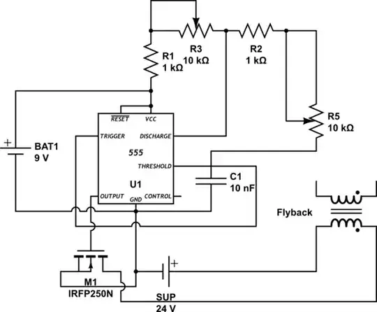
[Edit: Spectator added the following redrawn schematic] enter image description here

gwideman
  • 2,679
  • 13
  • 19
AvZ
  • 317
  • 1
  • 5
  • 17
  • Ain't that FET the wrong way around? – Dzarda Apr 18 '14 at 07:28
  • My bad, It is the wrong way. – AvZ Apr 18 '14 at 07:35
  • Now it is the right way. Edited. – AvZ Apr 18 '14 at 07:38
  • 1
    what frequency are you switching at and what load is across the transf. output. A load is needed to dampen back emfs and, these are likely to be destroying the 555 by being capacitive coupled thru the several hundred oF drain-gate capacitance of the fet. – Andy aka Apr 18 '14 at 10:07
  • Are you using a CMOS 555? You need good layout for this sort of thing. Power in should go directly to the MOSFET source, and only from there to the 555. A gate resistor of 20 ohms or so would not hurt. Don't even try this on a solderless breadboard. – Spehro Pefhany Apr 18 '14 at 12:19
  • Please please give this a read: http://electronics.stackexchange.com/questions/28251/rules-and-guidelines-for-drawing-good-schematics. It helps all of us, including you. – gwideman Apr 18 '14 at 14:58
  • 1
    I think I did add a 10 ohm resistor between the gate and the 3 pin (Output). – AvZ Apr 18 '14 at 15:21
  • I think you may need to add some power supply protection from being stuffed with hundreds of volts from coil. Capacitor in power supply will blow up at some point. – Kamil Apr 18 '14 at 17:09
  • Is C1 supposed to be connected to 555-THRESHOLD input? – gwideman Apr 19 '14 at 02:31

4 Answers4

2

The voltage spike created by the leakage inductance of your transformer is breaking down your MOSFET each time it switches off. You need to limit this voltage somehow; the usual technique is to put an R-C snubber across the source and drain of the MOSFET, sized so that the capacitor captures the energy of the spike before the voltage rises too high.

The values required depend very much on the characteristics of your specific transformer, so you'll have to do some experimentation to determine them.

One way to start is to find the value of the peak primary current in the transformer; the resistor should be sized so that this current, multiplied by the resistance, gives a peak voltage that's comfortably less than the rating of the MOSFET.

At the moment the MOSFET switches off, the drain voltage initially spikes high because of the leakage inductance of the transformer, but then it settles down to a voltage that's proportional to the secondary voltage (by the turns ratio of the transformer). The capacitor needs to be sized so that it charges to that voltage level in a time that's somewhat longer than the duration of the spike. This depends on both the inductance value and the resistor value. Be conservative at first (i.e., use an over-large value) and then fine-tune it (for better efficiency) once you have the circuit working.

Dave Tweed
  • 168,369
  • 17
  • 228
  • 393
  • I read about the RC snubber on a website... I think they gave some values too. I'll try. By the way, hopefully I won't blow the MOSFET if the values are not well suited? – AvZ Apr 18 '14 at 15:23
1

The IRFP250 is a relatively rugged FET (and one of my 'favourites'). You usually need to do something fairly robust to destroy them.

(1) You don't show a load or say that you have one. You probably do have one but, if not then Vout will rise until the energy stored in the inductor ('e' = i^2L) is either dissipated or stored in some other way. If breakdown of the FET or dissipation elsewhere does not occur then energy will be stored in the output capacitor (if present) and stray capacitance such that e = 0.5 x C x V^2. For small C, V can be very large.

(2) "Miller capacitance" coupling from drain to gate can induce voltages on the gate which are larger than the FET's Vgs_max rating. These are also applied to the driver output pin which will tend to clamp them, but the FTE is liable to be more sensitive to being destroyed if the voltage rises too high. Once the gate is broken down the FET may be driven into destruction - you can get D-S shorts with open gate (less common in my experience), and D-S-G shorts. This problem can be overcome by placing a reverse biased zener diode from dat to source with Vzener > Vdrive_max and less tha Vgs_abs_max. In this case, with a 12V supply, z 1V zener would be appropriate.

I have had circuits with this problem that died in minutes with no zener present and which operated indefinitely with a zener equipped. This is such a useful and effective protection system that I would fit a zener in most cases - but certainly would if there was any chance at all of there being an unprotected inductive load element present.

Russell McMahon
  • 147,325
  • 18
  • 210
  • 386
0

I use the irfp250, and don't have this problem, do you have a lot ad of some sort?, without one the back EMF will destroy mosfet's quite quickly

-1

Another classic fix for this problem is a flyback diode. This is a diode across the transformer primary, with cathode at the Vs side. When FET turns off, the transformer energy gets dumped into the power supply, and the FET voltage is clamped to just above the power supply voltage. Be sure to use an ultrafast diode - regular rectifiers won't do the job. Also, physical layout is important. The diode must be close to the FET. Like Spehro says, don't even think about using a solderless breadboard.

WhatRoughBeast
  • 59,978
  • 2
  • 37
  • 97
  • I actually had a fast diode on the circuit. The MOSFET still died. I don't remember the exact part number, but it had a reverse recovery time of something like 100nS. – AvZ Apr 18 '14 at 16:02
  • 2
    That kind of kills the whole point of having a flyback converter in the first place. If you dump all of the primary energy into the diode, how do you get anything out of the secondary? The primary voltage has to be allowed to rise to the level that gives you the desired voltage on the secondary. – Dave Tweed Apr 18 '14 at 16:39
  • It was reverse biased – AvZ Apr 19 '14 at 18:02