8

(Disclaimer in case it isn't painfully obvious - I'm very much a n00b, especially when it comes to understanding transistors).

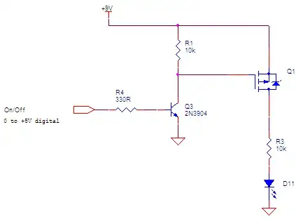
I thought I had it all figured out - a p-channel MOSFET is (or can be used as) a high-side switch for a different voltage source than what my MCU is running on. To test my understanding, I put together the following on a breadboard:

schematic

simulate this circuit – Schematic created using CircuitLab

The code on U1 (a 5V arduino) let me drive the line high or low, or put it in a high-z state to simulate all 3 scenarios. I expected that driving the line low would light the LED at 9V, and driving it high would turn the LED off (0V on the mosfet drain). What actually happened was - no light at all, and the drain having a voltage of 6V (5.9V). I'm quite confused - what's going on here?

Here's the mosfet I'm using: https://www.sparkfun.com/datasheets/Components/General/FQP27P06.pdf

It's meant to be controlled by even a 3.3V logic level, so 5V should be just fine.

kolosy
  • 2,288
  • 6
  • 29
  • 51

3 Answers3

11

There is an error in the O.P. circuit. It will not be able to turn off the LED, so the LED will be on all the time. To turn off the P-channel MOSFET, you need to pull the Gate to Source. The Source is always at +9V in your circuit, but the pullup R1 goes only to +5V (VCC).

A high side P-channel MOSFET switch often looks like this.

enter image description here

Q2 can be a small N-channel MOSFET or a small NPN transistor.

enter image description here

On the other hand, is there a reason for using a high side P-channel switch (as opposed to a low side N-channel switch)? Are you making this setup just to understand P-channel MOSFETs better?

Nick Alexeev
  • 37,739
  • 17
  • 97
  • 230
  • 1
    yes, this is just for understanding – kolosy Apr 15 '14 at 17:58
  • 1
    out of curiosity - why is the pull-down on the n-channel 100k, and the pullup on the p-channel 10k? – kolosy Apr 15 '14 at 18:09
  • @kolosy The size of the pull-up R1 determines how quickly Q1 will turn off. Gate capacitance of Q1 is discharging through R1. Both pull-up and pull-down can be 10k (especially if you are not shooting for very low power operation). – Nick Alexeev Apr 15 '14 at 18:23
  • It may be worth pointing out that some microcontrollers have pins that can be configured open-drain, and can accept a voltage outside of VDD, so that the driver circuit is "rolled in" to the device. – Kaz Apr 15 '14 at 23:06
  • @Kaz Can you post a link to a μC that has this kind of open-drain output? To date, I haven't yet seen or heard of a μC that do what you're describing. – Nick Alexeev Apr 15 '14 at 23:22
  • @NickAlexeev RA4 pin on older PIC16's, as an example. – Kaz Apr 16 '14 at 00:39
  • 1
    i just breadboarded the bottom version, using a 2N3904 NPN, a IRF9540 PNP mosfet, driving a 50W LED. Controlled by a schmitt NAND oscillator. Works great! – johny why Nov 14 '17 at 02:39
  • @NickAlexeev "Are you making this setup just to understand P-channel MOSFETs better?" In my case, reason is that uC is booting with HIGH state on a certain available pin, which turns ON the external device for some short period. Solution for me was to use NPN to drive PNP that is providing higher side (above uC's) Vcc to the device. – Vladimir Djuricic Dec 25 '20 at 07:23
7

There are a few things to change in your circuit:

  1. You want to pull the MOSFET gate to 9V, not VCC.

  2. Once you do this, you can't use the LED_EN pin directly, because it likely won't be 9V-tolerant.

  3. To fix this, you can use an N-channel MOSFET to pull down the gate of the P-FET.

  4. You'll need a current-limiting resistor on the LED.

Here's a diagram I did for another answer:

PMOS

This is driving a motor, but the same circuit works for driving an LED (with an additional resistor). I think the linked answer will give you some good info, too, if I do say so myself! :)

Good luck.

bitsmack
  • 16,747
  • 9
  • 52
  • 108
  • cool - your other post was definitely very helpful. – kolosy Apr 15 '14 at 18:15
  • @kolosy Glad to help :) – bitsmack Apr 15 '14 at 18:19
  • one more follow up? the real circuit that i was doing this in prep for is a mosfet hbridge, with two p and two n-channel fets. the battery voltage there is 6V, and the MCU is still a 5V ino. If the pull-ups on there are correctly pulling up to 6V, not vcc, do I still need the n-channel, or is a 1V difference something the ino can handle? – kolosy Apr 15 '14 at 18:24
  • 1
    @kolosy It really depends on the microcontroller. Generally, you don't want the I/O pins above VCC (or below ground). You may get away with it. Look in the datasheet under Absolute Maximum Ratings. These give the limits that will prevent the chip from damage, but it's not guaranteed to work outside of the recommended values. It often will :) An H-bridge has some intricacies. For example, the turn-on and turn-off times of the FETS have to be taken into consideration. If you turn one on at the same time as you turn another one off, you may get the case where one starts to conduct before... – bitsmack Apr 15 '14 at 18:37
  • ... the other one stops. This short circuit can be a problem! Some microcontrollers (PICs, for one) have a programmable dead-band setting, and will handle these timing issues for you. Good luck! – bitsmack Apr 15 '14 at 18:39
2

Your circuit as is won't work at all. It should always be in the on state because you always have a Vsg>Vthreshold. What you need is the 10k resistor attached to the 9V line, but that will only work if your 5V logic block can block up to 9V in the high-Z mode. Basically, the PMOS will shut off when the high-side is at the same voltage as the gate. The pmos will turn on when the gate voltage drops ~0.7V (Vthreshold) below the source voltage.

To turn on you'll want to drive high-Z and to turn off you'll want to sink the gate voltage down to 0.

horta
  • 12,738
  • 22
  • 45