1

I have 2 x 2N2222 BJTs powering 2 relays of 200mA each.

I am using 2 output pins with 500ohm resistors to power the transistors.

After powering it the circuit not working well, while replacing the relays with LEDs works well.

So I want to try and replace the 2 BJTs with 1 power FET. I have an IRFZ44N.

But after reading articles about the transistor, it seems like I cannot use it at all - looks like the gate needs +20V to work, while my AVR output 5V.

Is this true, and if so, what can I do?

JYelton
  • 32,302
  • 33
  • 134
  • 249
gabi
  • 343
  • 2
  • 5
  • 17
  • You can use the mosfet to drive the two relays with a Vgs of about 5V. Please refer to http://electronics.stackexchange.com/a/106428/33841 to see how you can figure out a proper Vgs level for any mosfet. – alexan_e Apr 15 '14 at 14:11
  • If you want to cheat, you can use a high side driver IC (e.g. BSP452). Possibly even to replace the relay – Will Apr 15 '14 at 14:25
  • The real issue is that "it's not working very well". Well, why not? What is wrong? 2N2222 transistors ought to be able to deliver 200 mA and be easy to turn on from the AVR. Please document the problem with schematics and specific key observations and measurements. Otherwise, "unclear what you're asking". – Kaz Apr 15 '14 at 21:31

1 Answers1

5

That part needs 10V to turn on to a guaranteed resistance. It's shown in this part of the datasheet:

enter image description here

20V is the absolute maximum (never exceed) value for the voltage.

It's also a beast of a MOSFET to replace a 2N2222A. To operate from a 5V input, you need a "Logic Level" MOSFET. A 2N7000 (TO-92) or 2N7002 (SOT-23) might work for you, but personally, I like some of the Alpha Omega parts such the AO3422 (SOT-23). It's not only rated for 55V and >2A, but it will also work well with 3V drive.

enter image description here

Edit: Vgs rating, as I said above, is an absolute maximum rating. You must never drive the gate beyond 12V in either direction with respect to the source. It has nothing directly to do with what it takes to turn the MOSFET on or ensure that it is off.

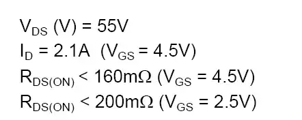
For that, you need to look at the Vgs for Rds(on) specification. The spec says it will have a resistance of < 160m\$\Omega\$ if you drive it with 4.5V (5V will be at least as good). So, at 200mA, you'll have a voltage drop of only 32mV, pretty close to a perfect switch. It's also pretty good with only 2.5V drive.

enter image description here

You also need to know what it takes to turn the MOSFET off, and the threshold voltage Vth gives you a clue:

enter image description here

250uA is not completely off, so you want to get well below 600mV on the gate to ensure it's fully off, although typically 1V would be okay. Any CMOS output will easily do this, unless you're sinking a lot of current through it for some other purpose.

Spehro Pefhany
  • 376,485
  • 21
  • 320
  • 842
  • on the AO3422 I can see Vgs is +-12V, how can I use it for 3 or 5V? Can you explaing the Rds parameter please? It is the R of the relay or some internal resistance? – gabi Apr 15 '14 at 14:30
  • th 2N7000 is 200mA Id (which means I cannot use any relay that takes more than that right?) , and my 2 relays are 400mA.. – gabi Apr 15 '14 at 14:33
  • 1
    He already has the mosfet he mentioned and for two 200mA relays it doesn't really matter if the Rds-on is not very low. With Vgs=5v, Rds-on will be about 0.025 Ohm (or 0.1 Ohm with Vgs=4.5V) which is fine for the specific task. – alexan_e Apr 15 '14 at 14:40
  • @alexan_e I don't see a guarantee of the Rds(on) at 5V on the datasheet. – Spehro Pefhany Apr 15 '14 at 14:43
  • @gabi Yes, if you need to drive 200mA x 2, the 2N7000 is insufficient. – Spehro Pefhany Apr 15 '14 at 14:43
  • What is the Rds? How it related to the Vgs? – gabi Apr 15 '14 at 14:47
  • 1
    @Spehro alexan_e is refering to Figure 1 (or 2) where you could infer Rds-on. Agreed that the mosfet is overkill, but what he has will work for his app. gabi Rds is the "ON" resistance from Drain to Source of the mosfet. So when you turn it on, it acts like a small resistor between those two points. The higher you make Vgs, the lower the resistance will be between D and S. – horta Apr 15 '14 at 14:59
  • @horta I know what he's referring to, and it's not guaranteed by the specifications, so if it works, it's luck. Vgs(th) 250uA could be as high as 4V, so if the drive is 4.5V, you're betting it gets high enough with delta 500mV. Might be an excellent bet, but I think it's bad engineering. – Spehro Pefhany Apr 15 '14 at 15:11
  • 1
    @SpehroPefhany Ah, I see what you're saying. This makes light of the difference between business work and hobbyist work. In one case, millions can be at stake, so your point is well taken. – horta Apr 15 '14 at 15:17
  • Where can I find the Rds on 5V Vgs? alexan_e said it is 0.025ohm but I did not find it anywhere on the datasheet. Just to be sure, the MOSFET will work with any voltage between Vgs-th to Vgs? so in my case from 4V to 20V? and I need to hold it under Min Vgs-th (2V in my case) in order to get 0A through drain-source? so I can put 10K resistor between gate and GND? – gabi Apr 15 '14 at 16:35
  • won't it get hot with 5V on the gate? I just read it somewhere.. :/ – gabi Apr 15 '14 at 16:36
  • I don't understand why the graphs in figures 1 and 2 of the datasheet are considered useless/random and the only specification that is considered valid is the one given for Vgs=10V. It's usual for manufacturers to provide the Rds-on value spec with a Vgs that shows the device at "it's best" but that doesn't mean that any other lower Vgs is useless. Since there is no graph that shows Rds-on vs Vgs , figure 1 is the closest to the device behaviour. @gabi I calculated the value from the values of figure 1 in page 3 of the datasheet. – alexan_e Apr 15 '14 at 16:44
  • @alexan_e They're not useless. You can use them in conjunction with the guaranteed value, especially to interpolate. Extrapolation is risky. – Spehro Pefhany Apr 15 '14 at 16:46
  • so on fig.1 I can understand that with 5V on the gate, and 5V from source to drain I can power 20A? which means the R=5/20=0.25ohm, right? – gabi Apr 15 '14 at 16:48