0

I've got a funny problem with interrupts and PWM signals that's causing false interrupts to trigger. What exactly is happening is that I'm using a hardware debounced quadrature rotary encoder. The pulses from the encoder are connected to interrupts which then I can determine the direction of rotation. Pretty standard routine. This works fine on it's own. Debounced Rotary Encoder

Now, I introduce a PWM output into my project. In this case, lets say I am dimming an LED. I load my program and the led works fine. When I rotate the encoder one "click", It appears that there are multiple interrupts that are triggered on the encoder..on the order of about 16 times the amount expected.

I've simplified the code all the way down and I've tried different different combinations of PWM and Interrupt pins and the response is always the same. The one bizarre thing I notice is that if I disconnect the jumper wire from the PWM pin to the LED, the problem goes away and the encoder starts behaving like it should. I'm baffled and can't figure out what's going on here?

How can I debug or test this? What's with the PWM jumper unplug and interrupts working properly? What does this sound like?

Also, I've asked this question on the Netduino and GHI electronics forums and haven't received any solutions.

schematic

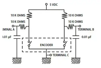
simulate this circuit – Schematic created using CircuitLab

Actual Circuit: Actual Circuit


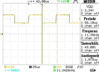
Update: Based on the help in the comments, I've uncovered that there is some type of noise induced in the PWM jumper wires which affect the jumper wires connected to the rotary encoder. When the PWM jumper wires are near the encoder jumper wires, the problem condition exists. How to I eliminate this noise, other than keeping the jumper wires apart from each other. Furthermore, how do you eliminate this noise in the case of PCB traces?

GisMofx
  • 357
  • 5
  • 19
  • My guess is that you have a layout problem. The currents flowing in the PWM circuit are causing ground bounce, coupling, or level shifting such that the interrupts get triggered. Better layout, decoupling and routing of the high current and high dv/dt signals should solve there problem. – John D Apr 14 '14 at 18:06
  • Have you got an oscilloscope you can look at the signals with? That would be a good start. – John U Apr 14 '14 at 18:42
  • What amount of current does the LED draw and how is it connected to the Netduino? Did you use extra decoupling around the LED driver? Also take a look at this http://electronics.stackexchange.com/questions/90971/does-my-circuit-need-decoupling-caps – jippie Apr 14 '14 at 19:09
  • @JohnU I'm working on getting an oscilloscope ASAP, BUT I do have a logic analyzer which shows the expected behavior for each click of the encoder. I recognize an oscilloscope is really what I need, but FWIW the logic analyzer giving expected results. – GisMofx Apr 14 '14 at 19:14
  • What exactly are we seeing in your diagram? I'm assuming: A and B are connected to your input pins, C is connected to ground? – John U Apr 14 '14 at 19:22
  • @jippie In this case, the LED is simply connected a header pin to a breadboard, through the LED, and a jumper back to ground. I'll read through that other question...Where would the decoupling resistor cap go for this simple example? Across the LED? – GisMofx Apr 14 '14 at 19:26
  • @JohnU I'm making a circuit diagram my this setup, but yes you're correct. A and B are connected to the two interrupt pins I've defined and C is ground. – GisMofx Apr 14 '14 at 19:39
  • You should add a diagram of how the LED is connected to the controller to your question, it is not 100% clear now. If it is just an LED directly connected to the controller, did you think of the **series resistor** to limit current? And you must not decouple just the LED, look at the diagram in my answer, you decouple LED + transistor, but that is only possible when using an external driver transistor. – jippie Apr 14 '14 at 19:39
  • You can add a circuit by hitting Ctrl-M while editing the question. A circuit editor will open. – jippie Apr 14 '14 at 19:41
  • @jippie thanks for the tip..that's a great feature! Circuit added. – GisMofx Apr 14 '14 at 20:28
  • Start by adding a 220 ohm series resistor to the LED. You are overloading both the LED and the microcontroller output pin. – jippie Apr 15 '14 at 04:52
  • @jippie I did. Same behavior exists. Circuit diagram has been updated. – GisMofx Apr 15 '14 at 13:02
  • How about posting a photo of your circuit, as the diagram doesn't show everything. – John U Apr 15 '14 at 15:20
  • @JohnU Circuit Photo Added. – GisMofx Apr 15 '14 at 15:32
  • @jippie Ah! Some positive results! ...I can't explain, what changed other then the time, ha, but NOW testing the circuit with the series resistor with the LED it works!.If I bypass the resistor, the interrupts again get funky!....I will update my question/circuit, because the actual "load" is using the PWMs as a clock signal (GSCLK) and Blank pins for a TLC5940 chip. Would adding series resistors there do the trick?(I'll try) – GisMofx Apr 15 '14 at 20:32
  • I started moving the jumper wires around and fiddling with them. I discovered that when the PWM jumper is less than 1" away from the encoder jumpers, the interrupts start to get funky. The closer the PWM jumper, the greater the encoder interrupt junk. Also, I tried this with and without the series resistor with the LED and the resistor does help a significant amount. Some kind of field from the PWM jumper making noise on the encoder wires? – GisMofx Apr 15 '14 at 20:43
  • Decrease R3/R4. Not sure why you use them anyway. Only R1/R2 are required. – jippie Apr 16 '14 at 04:50
  • And stop bypassing the resistor, you'll kill the microcontroller sooner or later. – jippie Apr 16 '14 at 05:35
  • @jippie - R3/R4 limit the instantaneous current through the encoder contacts. They are a good idea. Without them, the entire C1/C2 charge is dumped as soon as the switch makes contact. Also, they make the debouncing symmetric. Otherwise, you have asymmetric pull-up and pull-down resistances (this is true anyways, R1 vs R1+R2), but 2X difference is much less then 100X or more without R2. – Connor Wolf Apr 16 '14 at 07:55
  • @ConnorWolf R1/R3 puts the output voltage from the encoder right at 1/2 Vcc at worst, which is the trigger threshold for an AVR. A slight bit of noise wil make the input see an intermittent signal. – jippie Apr 16 '14 at 12:01
  • @jippie - What? No that's not how it works. The inputs are high impedance. It's not a divider like that. It'll either charge up to Vcc, or be pulled down to 10K/R\$_{Switch}\$. – Connor Wolf Apr 16 '14 at 12:28
  • @jippie - the only thing R3, R4 affect is the charge/discharge rate of the capacitors. The DC steady-state voltage across them will be 0V. – Connor Wolf Apr 16 '14 at 12:29
  • @jippie so it seems like noise from the PWM signals are the culprit. What's the best way to avoid this during prototyping and also in production of a PCB? – GisMofx Apr 19 '14 at 19:32
  • Lower impedance? Maybe @ConnorWolf has a more specific advise? You have to find a balance in sensitivity to noise and encoder endurance. Nice example of how different people have a different view on an issue. – jippie Apr 19 '14 at 19:48
  • Get C1 and C2 as close to the MCU pins as possible, and ensure they have an independent ground return to the MCU. Also, reduce R1 and R2 to ~1K, to make the charge/discharge of the caps more symmetrical. Lastly, software-debouncing as an additional precaution is probably a good idea anyways, as an additional layer of protection. – Connor Wolf Apr 20 '14 at 03:37

1 Answers1

1

Use software debouncing: In your interrupt routine deactivate interrupts (so no other interrupts after the current one are fired) and then set a flag, that the interrupt was called.

In your Main routine check for the flag, act on it and then enable interrupts again. Maybe add a small delay before enabling interrupts again.

This seems to be another solution to software debouncing:

 private static void Button1_OnInterrupt(uint data1, uint data2, DateTime time) {
        // glitch filter. events within 50 milliseconds of the first event are discarded
        if (Button1LastPushed.AddMilliseconds(50) > time)
            return;
        // Debug.Print("Button 1 Interrupt");
        Button1LastPushed = time;
        // actions on interrupt here
}

Of course you need to adapt it to your PWM.

PS: LEDs have a small backward current, this could be the source of your problem.

cgross
  • 181
  • 1
  • 5