SCROLL DOWN TO SEE THE SOLUTION (UPDATE II)
ORIGINAL POST: I am currently building a 433MHz remote with two buttons. The remote is controlled by an Attiny85v(8MHz). Sadly it does not work very reliable, sometimes it works other times nothing happens.
Here some explanations on what I did and why:
Each of the buttons triggers a pin change interrupt which wakes the Attiny from sleep. After that I check which button was pressed and turn on or off the lights via 433MHz switches. But those buttons don't work very reliable. Sometimes the do what they should other times I need to press them for several seconds before something happens. I don't know why, either I have a bug in my code or in the circuit for the buttons.
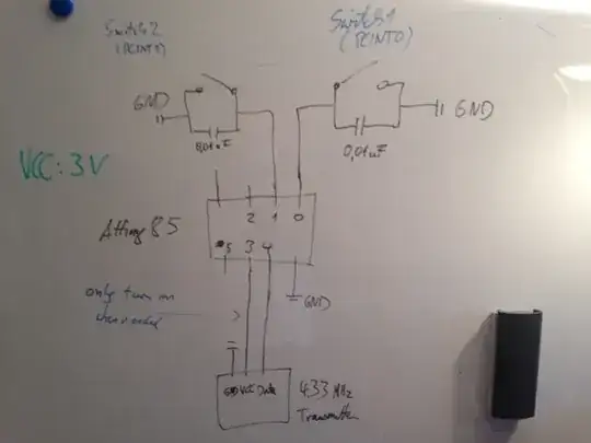
I use a 2.2k resistor to pull the button pins (0 and 1) to GND. When pressing the button, the pins will be pulled HIGH. To avoid "bouncing" of the tactile switch I added an 0.01uf capacitor in parallel.
I tried to keep the code simple and added comments. You can find it here: http://pastebin.com/hzw0j3FW
Here is my circuit:
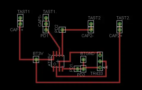
Eagle schema:
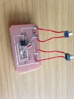
Front & back:

UPDATE: Thanks for all the feedback, I also received some feedback on a german forum. Here is a list of what is/could be wrong with the design:
- Don't pull the pins HIGH when pressing the buttons. Instead use INPUT_PULLUP and pull then to GND when pressing.
- As pointed out here, as well as in the forums: Either use a software debouncing or an inverted Schmitt-Trigger
- When using software debouncing make sure to only set flags in the interrupt routine and act on those flags in the loop routine.
- Test if the RF-transmitter has enough juice
- Add an capacitor across VCC and GND of the Attiny
- Try powering the whole circuit with a lab power supply. Maybe the coin cell can not provide enough power.
Sadly I flashed my last Attiny85v to death today, so it will take some time for me to fix this design. I will report back once I have a solution.
UPDATE II, Solution: IT'S WORKING. The design is flawed but it works. Here are the two 'bugs' I found.
Use high quality switches. I sourced my switches from Farnell but they were of very bad quality. You had to press them down an then move your thumb to make sure they connect. This was the reason why the remote only worked spontaneously.
The second problem was that not all rc-power-plugs were turned off when pressing the off button. Sometimes it would turn off all three of them, sometimes only one. This was because of the rf transmitter. As @Michal Canecky and @Ricardo pointed out those transmitters run on 3V+. They do work with 'only' 3V but the range is very limited (2m in my case). By soldering an 15cm antenna to the transmitter I was able to get a range of 3-4m. Now all rc-power-plugs turn off reliably.
I also used a scope to test if the coin cell was not strong enough by measuring the voltage of the transmitter during transmission. As it turned out it was fine and constant.
Thanks again for the tips.
Still the design is flawed, here is what I would improve or do again if I were to rebuild it:
Don't pull the pins HIGH when pressing the buttons. Instead use INPUT_PULLUP and pull then to GND when pressing.
Keep the capacitor over the buttons for debouncing. I used a scope to test if it works, and the results were solid. Make sure to not go over 0.01uF.
Add a capacitor between VCC and GND of the Attiny
In the code: Make sure you disable interrupts after receiving one, this also serves as a software debouncing of the buttons. This was already reflected in the original code. Don't forget to turn on interrupts before going to sleep ;)
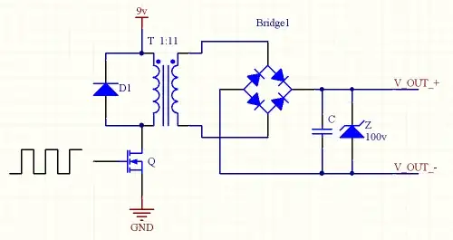
If you need a range greater than 3m, use a voltage doubler (thanks @Michal Canecky) or a power source with more than 3V. Use the Attiny to turn the voltage doubler off after transmission.
Add a capacitor parallel to the battery to improve battery life, especially for noname vendors. This is only needed if your circuits peak current is above 10mA. Have a look at this excellent article from TI. It also explains how to calculate the capacity.
This is what the code of this improved version would look like Code v2 (Note: I did not test this code)
Here the updated circuit that I would use: